Adjustment features and input 5, Preliminar y, Front panel features and basic operation, cont’d – Extron Electronics System 5 IP Series User Guide User Manual
Page 30
Front Panel Features and Basic Operation, cont’d
System 5 IP Switchers • Front Panel Features and Basic Operation
3-4
PRELIMINAR
Y
5
Function/room control buttons
— These buttons can be set up to control the
switcher’s relays, and they can also be set up to execute IR or RS-232
commands of your choice. The relays can be used to control items in the
room such as a projector lift, screen motor, or lighting. For details on how the
relays operate and can be configured, see the installation instructions in
chapter two and the configuration software information in chapter four.
Three function buttons are available on the System 5 IP FPC model, but both
models have a virtual fourth function button that can be accessed via
software, an optional SCP, or the embedded Web page.
6
Input selection buttons
— Press one of these buttons to select the desired
audio and video input. The button lights brighter and remains lit while an
audio-video input is selected. During audio breakaway (selectable only with
SIS commands via RS-232 or Ethernet control), audio is switched separately
from video; the selected video input’s button lights steadily, and the audio
input’s button blinks. (See page 5-8 under “Input selection” for how to select
A/V breakaway.) As with
4
and
5
, other functions and relays can be
associated with each of these buttons via the Global Configurator software.
7
Menu
and Next buttons — See the description and illustration below.
10
Input 5 selection button (non-FPC model only)
— Press this button to switch
to input 5. Press this button again to deselect input 5 and return to the
previously selected input.
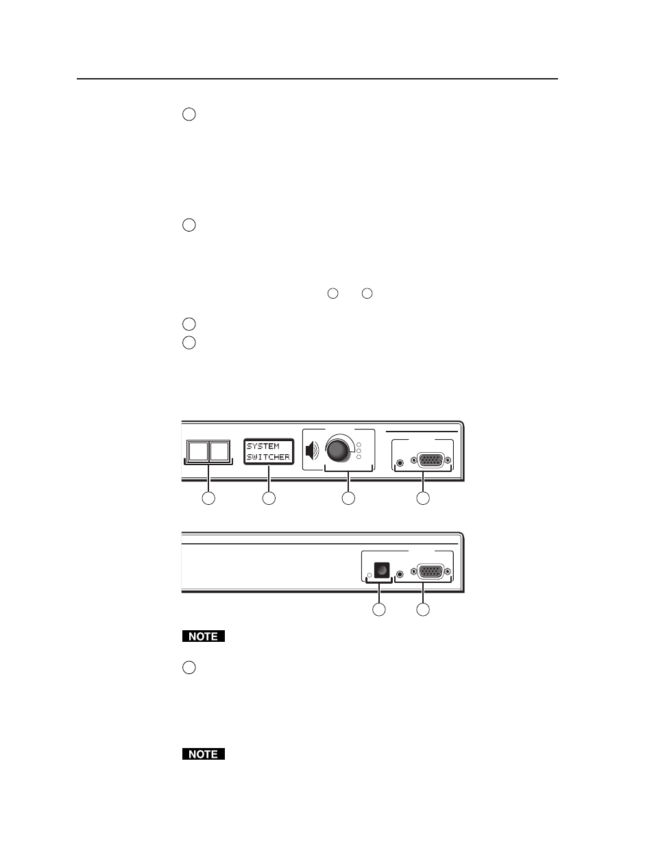
Adjustment features and input 5
SYSTEM 5 IP
MENU
NEXT
PC VIDEO
INPUT 5
MAX
MID
VOLUME
AUDIO
ADJUST
MIN
SYSTEM 5 IP
PC VIDEO
INPUT 5
AUDIO
11
11
9
7
8
10
System 5 IP with FPC
System 5 IP without FPC
If you adjust volume, gain, bass, or treble, it takes 1 minute 40 seconds
(100 seconds) for data in the switcher’s RAM to be saved to flash memory.
7
Menu
and Next buttons — Press these buttons to access and navigate
through the switcher’s LCD menus and options. For details, see “LCD Menus
and Basic Switcher Setup” on page 3-8. These two buttons light only when
they have been pressed, during switcher setup. They are not user-
programmable/configurable. To disable any of the front panel security
lockout modes (executive modes), press the front panel Menu and Next
buttons simultaneously for about three seconds.
Video output may turn off briefly (for the duration of the RGB delay setting)
while you set the video configuration for inputs 1 and 2 or when you press the
Menu and Next buttons and enter the Video Config menu.