Rear panels and cabling, Power, a/v input, and video output connections, Power, a/v input, and video output connections -4 – Extron Electronics System 5 IP Series User Guide User Manual
Page 14: Preliminar y, Installation: labeling, mounting, cabling, cont’d, Rgbhv composite video s-video, Unbalanced stereo input, Balanced stereo input, Unbalanced mono input, Balanced mono input
Installation: Labeling, Mounting, Cabling, cont’d
System 5 IP Switchers • Installation: Labeling, Mounting, Cabling
2-4
PRELIMINAR
Y
V
H
C
Y
R
/VID
G
/Y
B
/C
V
H
R/
VID
G/Y
B/C
V
H
R/VID
G/
Y
B/
C
RGBHV
Composite Video
S-video
Rear Panels and Cabling
Power, A/V input, and video output connections
100-240V 1.3A
50-60Hz
Tx Rx G
G
S G
S
G
S G
S G
G
Ps
+V
+V
CM IR SCP
R
Y/C
G
Y
B
V
H
VID
Y/C
VID
C
Y
R/VID
G/Y
B/C
H
V
C
VID
V
H
R/VID
G/Y
B/C
INPUT 1
INPUT 3
INPUT 4
INPUT 2
CM/IR/SCP
RS-232
PROJ CONT
AUDIO
IR/SERIAL OUT
E
C
B
D
A
L 1 R
L 2 R
OUTPUT
A
L 3 R
L 4 R
B
C
D
_
_
_
_
2
3
5
4
1
1
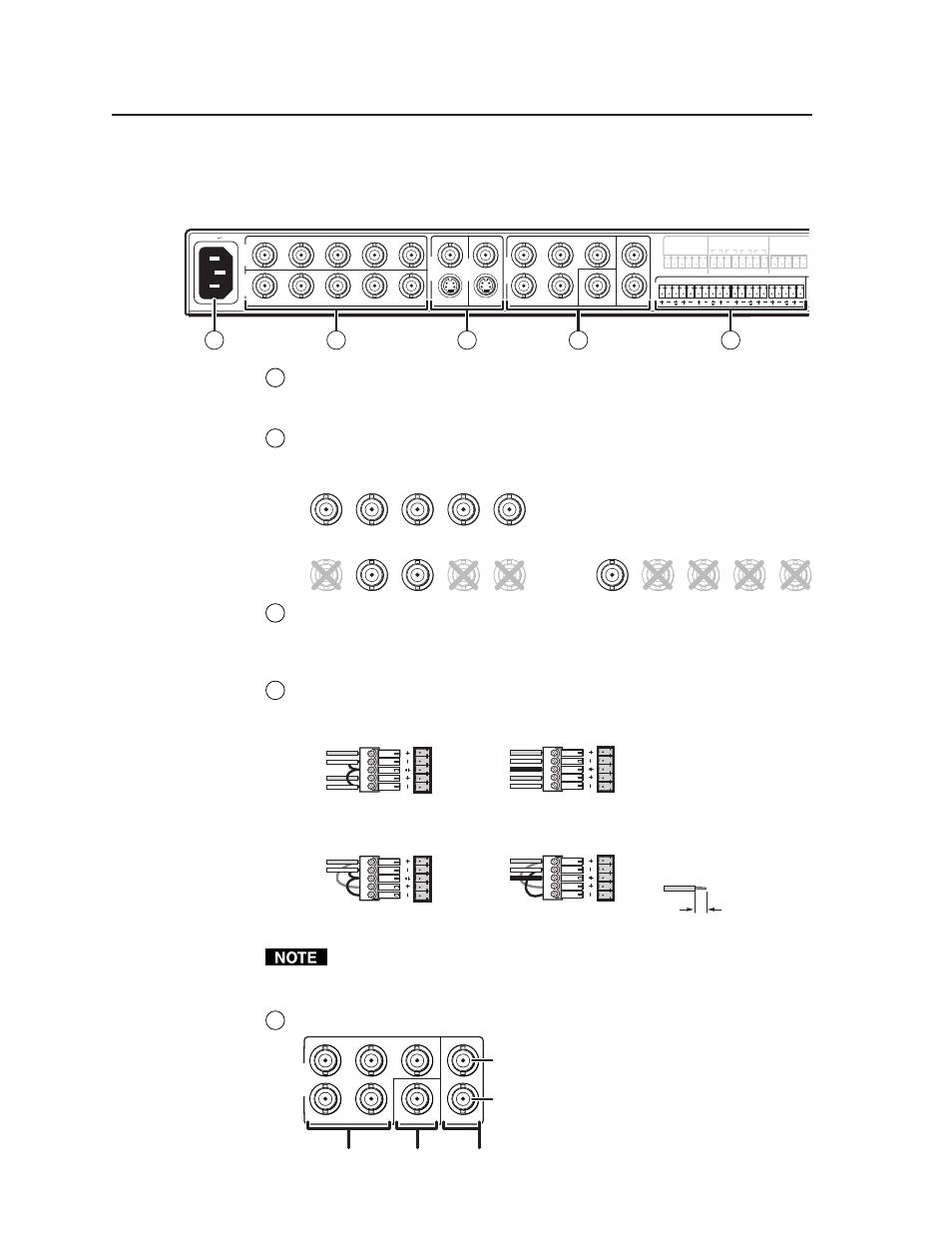
Power connector
— After you have completed the audio/video and control
connections, connect a standard IEC power cord from the AC power supply
to this connector.
2
Inputs 1 and 2: RGBHV/S-video/composite video inputs
— Connect cables
from an RGBHV, S-video (Y/C), or composite video source to each of these
inputs. See the diagrams below.
Inputs must be configured for either
video or RGB. See chapters three,
four, and five for details.
3
Inputs 3 and 4: S-video/composite video inputs
— Connect the cable from
either an S-video (Y/C) source (using the 4-pin mini DIN connector) or a
composite video (Vid) source (using the BNC connector) to each of these
inputs. Inputs 3 and 4 are not configurable.
4
Audio inputs
— These inputs correspond to the like-numbered video
inputs. For each input, connect the cable from a balanced or unbalanced
stereo or mono audio input source. See the wiring diagrams below.
LR
LR
LR
LR
Unbalanced Stereo Input
Tip
Sleeve
Tip
Sleeve
Balanced Stereo Input
Tip
Ring
Sleeve (s)
Tip
Ring
(high impedance)
(high impedance)
Unbalanced Mono Input
Tip
Sleeve
Tip
Sleeve
Balanced Mono Input
Tip
Ring
Sleeve (s)
Tip
Ring
(high impedance)
(high impedance)
0.2” (5 mm) max.
The length of exposed wires is critical.
The ideal length is 0.2" (5 mm).
• If the stripped section of wire is
longer than 0.2", the exposed
wires may touch, causing a
short circuit between them.
• If the stripped section of wire is
shorter than 0.2", wires can be
easily pulled out even if tightly
fastened by the captive screws.
Do not tin the wires!
After the audio inputs and outputs are connected, see pages 3-5 through 3-7,
and pages 3-9, 4-11, and 5-9 for instructions on how to adjust the per-input
audio levels.
5
Display outputs
— Cable these output BNC connectors to an RGBHV,
S-video (Y/C), or composite video
port on the projector or display. See
the diagram at left.
R
G
Y
B
H
V
C
VID
OUTPUT
RGBHV
Composite
Video
S-video
Y = luma
C = chroma