Control connections, Preliminar y – Extron Electronics System 5 IP Series User Guide User Manual
Page 19
2-9
System 5 IP Switchers • Installation: Labeling, Mounting, Cabling
PRELIMINAR
Y
Tx Rx G
G
Ps
+V
RS-232
PROJ CONT
System 5 IP
Rear Panel
Transmit (Tx)
Receive (Rx)
Ground ( )
To a
projector
or display
+12VDC
Ground ( )
Power
sense
Sleeve ( )
Ring
(signal)
Tip (+12V)
3.5 mm Stereo Plug
To an Extron
Power Sensor
(60-271-01)
Tx Rx G
G
Ps
+V
RS-232
PROJ CONT
System 5 IP
Rear Panel
Projector
Panel
Ground ( )
Receive (Rx)
Transmit (Tx)
Ground ( )
Receive (Rx)
Transmit (Tx)
Bidirectional
Control connections
_
_
+
_
LEFT
+
RIGHT
_
2
1
C
C
4
3
C
6
5
C
Tx Rx G
G
S G
S G
S G
S G
G
Ps
+V
+V
CM IR SCP
R
CM/IR/SCP
RS-232
2
PROJ CONT
RELAYS
IR/SERIAL OUT
E
C
B
B
D
A
A
L LINEOUT R
L PREAMP R
L 1 R
L 2 R
AMPLIFIED
OUT
4/
8
ohm
CONFIG/RS-232
LAN
A
L 3 R
L 4 R
B
C
D
4
5
6
1
2
3
1
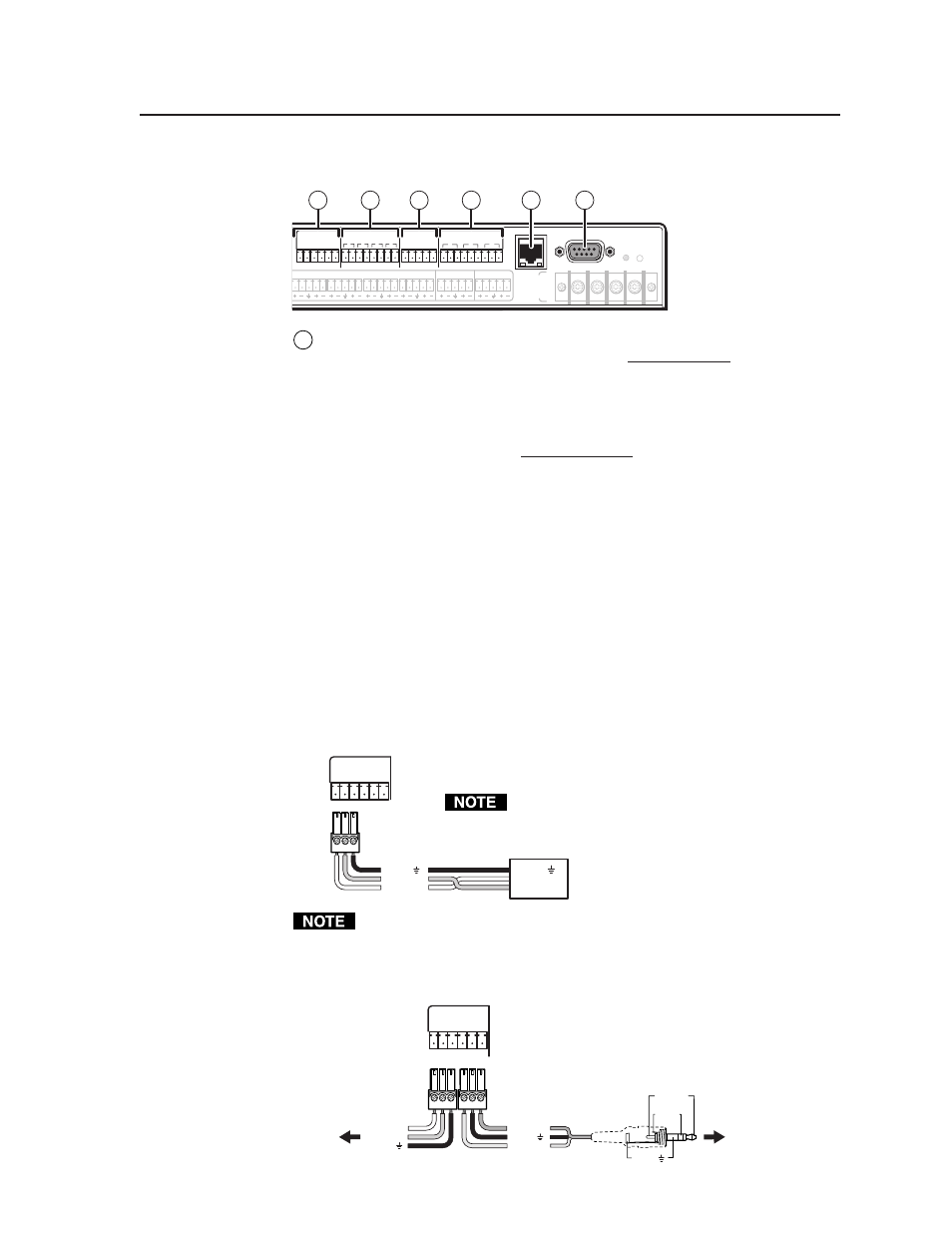
Projector control (Proj Cont) RS-232 port
(-5 VDC to +5 VDC) — Connect a
cable between the projector/display and the left three poles of this 3.5 mm
captive screw connector for RS-232 one- or two-way control. Commands
from a downloaded projector/display driver or user-defined command
strings entered via the configuration program can be sent to the display
device from this port.
Connect a cable between the right three poles of the Proj Cont port and
accessories such as an Extron Power Sensor. The Power Sensor can be used
to let the switcher know when the projector is on or off. If these pins are not
connected to a Power Sensor, the SNS and ground pins can be used for digital
input as can pin 1 and ground of the 9-pin D RS-232 Host Control port.
Digital input:
the power sense pin and the ground pin together act as a
digital input port (depending on configuration). This allows for an
additional way to trigger events or functions (such as triggering relays,
issuing commands, or sending an e-mail).
When configured as a digital input, this port will be in one of two states:
1 (on, high) or 2 (off, low). A closed circuit = a logic 1, an open circuit = a
logic 0. Threshold voltages are <0.6 VDC = low, >0.70 VDC = high.
Use the following illustrations as a wiring guide. Wiring varies depending
on the projector or display model. In most cases only the transmit (Tx) and
ground connections will be needed for projector control.
For bidirectional RS-232 communication, the transmit,
ground, and receive pins must be wired at both the
switcher and the projector/display.
Each projector or display may require different
wiring. For details, refer to the manual
that came with the projector/display.
Maximum distances from the System 5 IP to the device being controlled may
vary up to 200 feet (61 m). Factors such as cable gauge, baud rates, environ-
ment, and output levels (from the switcher and the device being controlled)
all affect transmission distance. Distances of about
50 feet (15 m) are typically not a problem. In some
cases the System 5 IP may be capable of transmit-
ting and controlling a given device via RS-232 up
to 250 feet (76 m) away, but the RS-232 response
levels of that device may be too low for the
System 5 IP to
detect.