Rs-232/rs-422 connection, Rs-232/rs-422.connection -6, Preliminar y – Extron Electronics MVX VGA A User Guide User Manual
Page 21: Installation, cont’d
Installation, cont’d
MVX VGA A Matrix Switchers • Installation
2-6
PRELIMINAR
Y
e
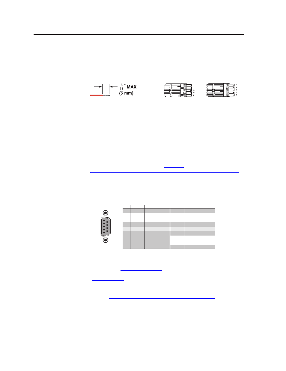
Connections for balanced and unbalanced audio outputs — These
3.5 mm, 5-pole captive screw connectors output the selected unamplified,
line level audio. Connect audio devices, such as an audio amplifier or
powered speakers. See figure 2-6 to properly wire an output connector. Use
the supplied tie-wrap to strap the audio cable to the extended tail of the
connector.
Unbalanced Stereo Output
Balanced Stereo Output
L
R
Do not tin the wires!
Ring
Sleeve(s)
Tip
Tip
Ring
Sleeve(s)
Tip
Tip
NO GROUND HERE.
NO GROUND HERE.
Figure 2-6 — Captive screw connector wiring for audio output
C
Connect the sleeve to ground (Gnd). Connecting the sleeve to a
negative (-) terminal will damage the audio output circuits.
C
The length of the exposed (stripped) portion of the copper wires is
important. The ideal length is 3/16” (5 mm). Longer bare wires can
short together. Shorter bare wires are not as secure in the direct insertion
connectors and could be pulled out.
The volume level for each output can be individually set via the front panel
or serial port control. See chapter 3, “Operation”, chapter 4, “Programmer’s
Guide”, and chapter 5, “Matrix Software”, for details.
RS-232/RS-422 connection
f
Remote RS-232/RS-422 connector — Connect a host device, such as a
computer, touch panel control, or RS-232 capable PDA to the switcher via this
9-pin D connector for serial RS-232/RS-422 control (figure 2-7).
RS-232 Function
Pin
Function
1
2
3
4
5
6
7
8
9
—
TX
RX
—
Gnd
—
—
—
—
Not used
Transmit data
Receive data
Not used
Signal ground
Not used
Not used
Not used
Not used
—
TX–
RX–
—
Gnd
—
RX+
TX+
—
Not used
Transmit data (–)
Receive data (–)
Not used
Signal ground
Not used
Receive data (+)
Transmit data (+)
Not used
RS-422
5
1
9
6
RS232/RS422
REMO
TE
Figure 2-7 — Remote RS-232/RS-422 connector
See chapter 4, “Programmer’s Guide”, for definitions of the SIS commands
(serial commands to control the switcher via this connector) and chapter 5,
“Matrix Software”, for details on how to install and use the control software.
N
The switcher can support either the RS-232 or RS-422 serial communication
protocol, and can operate at 9600, 19200, 38400, or 115200 baud rates.
See “Selecting the rear panel Remote port protocol and baud rate” on page 3-38,
to configure the RS-232/RS-422 port from the front panel.
If desired, connect an MKP 2000 or MKP 3000 remote control panel to the
switcher’s RS-232/RS-422 connector. Refer to the MKP 2000 Remote Control
Panel User’s Manual
or the MKP 3000 Remote Control Panel User’s Manual for
details.