Device connections, Display connection, Infrared (ir) connection – Extron Electronics MLC 104 Plus Series Setup Guide User Manual
Page 20: Digital i/o connection, Hardware setup, cont’d, Mlc 104 plus series • hardware setup, Ir emitter 1
MLC 104 Plus Series • Hardware Setup
Hardware Setup, cont’d
2-8
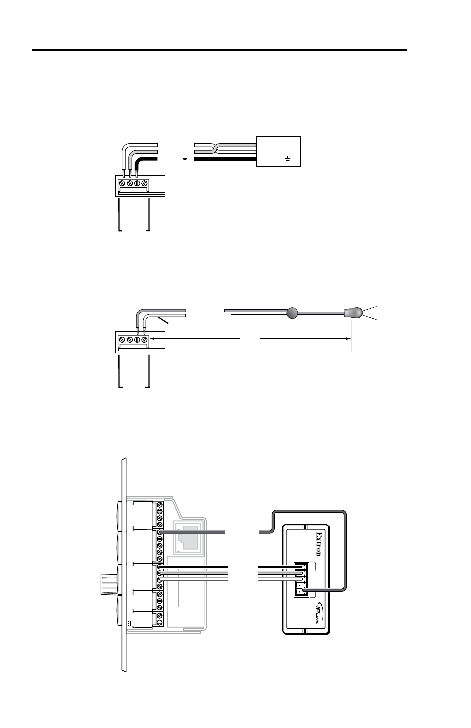
Device Connections
The following illustrations show examples of A/V and control
device connections for all models.
Display connection
Projector
Panel
MLC 104 Plus Series
Right Side Panel
DISPLAY
RS-232/IR
GR
OUND
IR OU
T
Tx
Rx
Ground ( )
Receive (Rx)
Transmit (Tx)
Ground ( )
Receive (Rx)
Transmit (Tx)
Bidirectional
Infrared (IR) connection
MLC 104 Plus Series
Right Side Panel
DISPLAY
RS-232/IR
GR
OUND
IR OU
T
Tx
Rx
G = Ground
IR Emitter 1
White Striped Wire
100'
(30.5 m)
S = Signal (IR)
Digital I/O connection
MLC 104 Plus Series
Right Side
IPA T RLY4
Front Panel
1
2
3
GROUND
+12V OUT
CM
GROUND
IR OUT
GROUND
SCP
GROUND
Tx
Rx
DISPL
AY
RS-232/IR
A B C D
E
COMM LIN
K
LAN
PRESS
TA
B
WITH
TWEEKER
TO
REMO
VE
A
B
MLS
RS-232
PO
WER
12V
DIGI
TA
L
I/O
IR IN
Tx
GROUND
Rx
+12V IN
IP
A
T RL
Y4
1 2 3 4
C
INPUTS
Relay 1
Relay 2
Relay 3
+12 VDC
- AVTrac Corner Cut Solution (2 pages)
- AVTrac Demonstration Kit (2 pages)
- AVTRac End Ramp and Cable Pass-Through Kits (1 page)
- AVTrac Extension Kit (15 pages)
- 1U and 2U Rack Plate (1 page)
- Under-Desk Mounting Bracket (1 page)
- AAP Wiring Guide 68-1054-01 (1 page)
- AAP Wiring Guide 68-1052-01 (1 page)
- AAP Wiring Guide (XLR connectors) (1 page)
- AAP 314 (1 page)
- AAP 301 (1 page)
- AAP Wiring Guide 68-1055-01 (1 page)
- AAP Wiring Guide 68-1058-01 (1 page)
- AAP Wiring Guide 68-1059-01 (1 page)
- AAP-MAAP Rev. A (1 page)
- AAP-MAAP Rev. D (1 page)
- MD Floor Box AAP Bracket Kit AAP 100 MD (1 page)
- AC 100 Power Module Series (1 page)
- AAP 103 Extron Ackerman AKM UK Faceplate Kit (1 page)
- ACMP 100 (2 pages)
- Active Audio AAP (1 page)
- AKM UK Series (4 pages)
- Audio AAP Wiring Guide (1 page)
- Audio Connector Rev. A (2 pages)
- Audio Connector Rev. G (1 page)
- AVTrac Extra Channel Kit (2 pages)
- AVTrac Raceway Transition (2 pages)
- AVTrac Retrofit Transition Adapter (2 pages)
- AVTrac Trim Ring-Rough-in Adapter (2 pages)
- AVTrac Above Floor (1 page)
- BB 1 (2 pages)
- BB 1000M (2 pages)
- BB 700M (2 pages)
- BB 710M (2 pages)
- Blank Rack Panel (1 page)
- BNC to 15-Pin HD (1 page)
- BNC-5 RC Termination (1 page)
- Cable Cubby 1200 (6 pages)
- Cable Cubby 200 (18 pages)
- Cable Cubby 300C (27 pages)
- Cable Cubby 500 (6 pages)
- Flexible Conduit Kit (2 pages)
- Cable Cubby Lid and Trim Ring Replacement Kit (for 300C, 300S, 600, 800) (1 page)
- Cable Cubby Setup Guide (4 pages)
- Cable Cubby Single Space AAP Bracket Kit (1 page)