Mlc 206 aap cutout t emplate – Extron Electronics MLC 206 AAP EC User Guide User Manual
Page 68
Dimensions, Templates, Replacements, Upgrades, cont’d
MediaLink Controllers • Dimensions, Templates, Replacements, and Upgrades
B-4
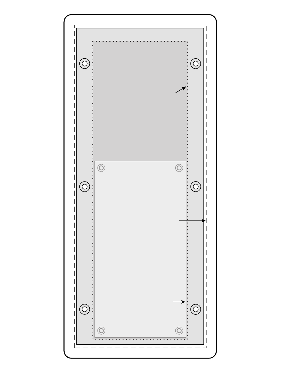
MLC 206 AAP Cutout
T
emplate
The light g
re
y area
with the solid g
re
y
line indicates the
location of the MLC
T
o install the MLC 206 AAP
directly into fur
niture
, use the
cut-out area (2.8" H x 8.8"
W)
indicated b
y the dotted line
.
The medium g
re
y area represents the la
y
out of the
electr
ical bo
x (3.75" H x 9.3"
W) against
the rear of the front panel.
The dashed line indicates the cut-out area
(3.9" H x 9.5"
W) f
or installing
the electr
ical w
all bo
x.
This manual is related to the following products: