Replacing faceplates and labels, Replacing the faceplate, Replacing faceplates and labels -4 – Extron Electronics MLC 206 AAP EC User Guide User Manual
Page 12: Replacing the faceplate -4, Installation, cont’d, Medialink controllers • installation 2-4
Installation, cont’d
MediaLink Controllers • Installation
2-4
7a.
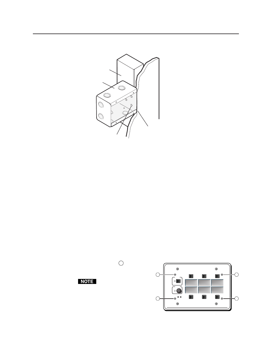
If you are using a wall box, insert the wall box into the opening, and attach it
to the wall stud/furniture with
nails or screws, leaving the front
edge flush with the outer wall or
furniture surface. The illustration
applies to all sizes of wall boxes.
Flush with
Wall Surface
Screws or Nails
Wall Stud
Wall Box
Extron
MediaLink Controller
MLC 206
DISPLAY
POWER
VOLUME
MAX/
MIN
VCR
DVD
Laptop
1
1
1
1
Attaching a wall box to a wall stud
If attaching the wall box to wood, use four #8 or #10 screws or 10-penny nails.
A minimum of 1/2 inch (1.3 cm) of screw threads must penetrate the wood.
If attaching the wall box to metal studs or furniture, use four #8 or #10 self-
tapping sheet metal screws or machine bolts with matching nuts.
7b.
If you are using a mud ring, follow the directions, if any, that came with the
mud ring to attach the clips that fasten the ring to the wall or furniture.
8.
If desired, replace the faceplate and/or input labels.
9.
Cable and test the MLC before fastening it into the wall box, mud ring, or
furniture.
Replacing faceplates and labels
The MLC’s faceplate and the backlit input selection labels can be replaced. You can
replace the standard faceplate with an optional lectern mounting, rack mounting, or
wall mounting MLM faceplate for installation into a variety of locations. The
MLC 206 is shown in the following examples, but the instructions apply to all
models.
Replacing the faceplate
1.
Use a small Philips screwdriver to remove the four faceplate attachment
screws marked
1
in the
picture at right, and keep them
for later use.
Do not remove these screws
while the MLC is installed
in a wall or furniture, or the
controller may fall down
into the wall/furniture or
wall box.
2.
Lift the faceplate off the MLC.
3.
Align the openings in the new faceplate with the controller’s buttons, knobs,
and LEDs, and place the new faceplate on the MLC.
4.
Replace the four screws removed in step one, and hand tighten them.