5 medialink controllers • serial communication – Extron Electronics MLC 206 AAP EC User Guide User Manual
Page 37
4-5
MediaLink Controllers • Serial Communication
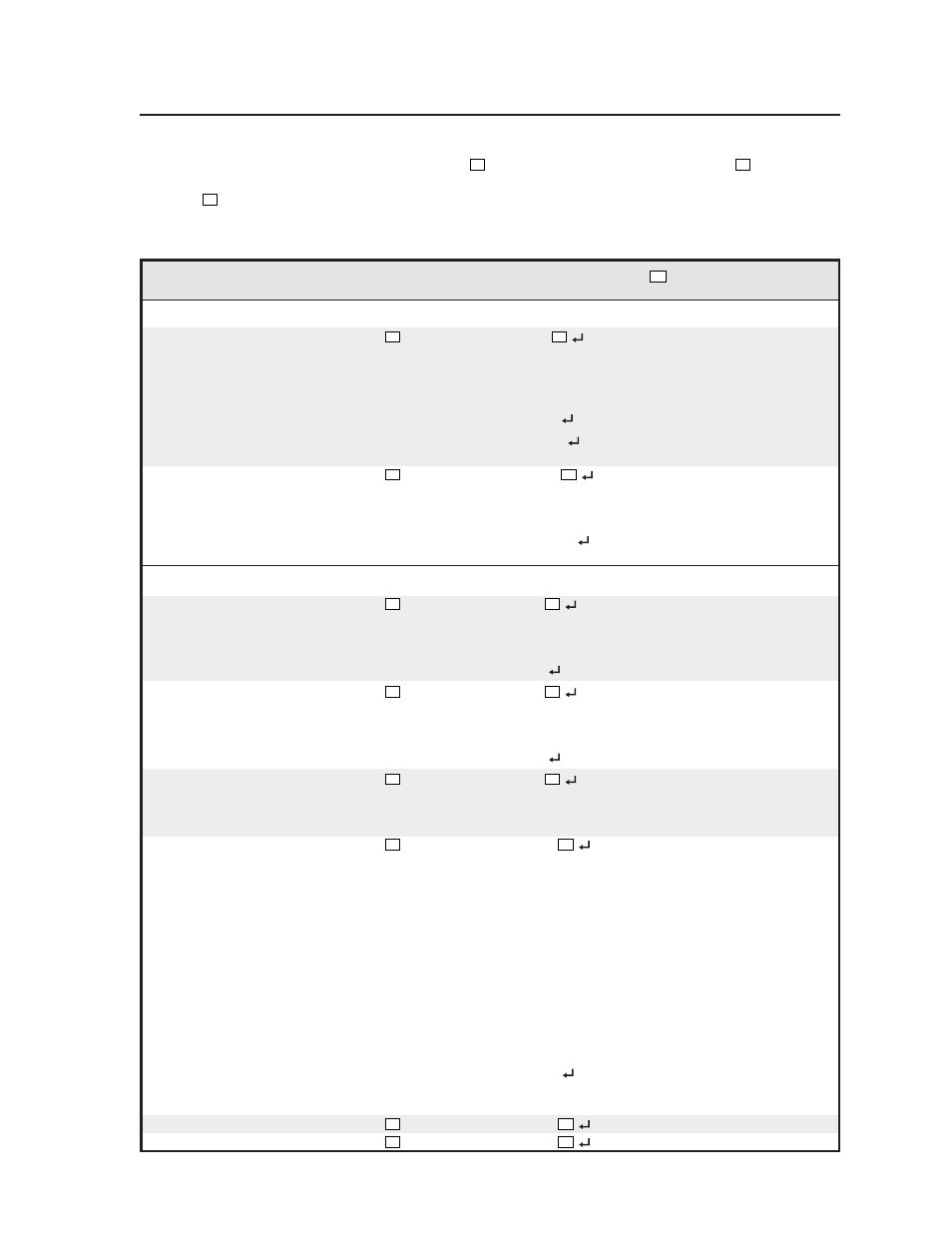
The syntax for setting a special function is __ *
X?
# where __ is the function number and
X?
is the value.
To view a function’s setting, use __#, where __ is the function number. In the following table the values of
the
X?
variable are different for each command/function. These values are given in the rightmost column.
Command/response table for special function SIS commands
Command
ASCII Command Response
X?
values
(host to MLC)
(MLCr to host)
and additional descriptions
Delay times
Power on delay
1 *
X?
#
WarmUp*
X?
0 = 0 seconds,
1 = 2 seconds,
2 = 4 seconds,
... in 2 second steps up to
150 = 300 seconds (5 minutes).
Example:
1*8#
WarmUp*08
Example: set a 16 second power on delay.
Example:
1#
WarmUp*023
Example:
view the power on delay
setting.
Power off delay
2 *
X?
#
CoolDown*
X?
0 = 0 seconds,
1 = 2 seconds,
2 = 4 seconds,... in 2 second
steps up to 150 = 300 seconds.
Example:
2*23#
CoolDown*023
Example:
set a 46 second power off
delay.
Relays
Relay 1 mode/timing
4 *
X?
#
Rly1Tm*
X?
0 = toggle mode (press on/off),
1 = momentary, 1 second long,
2 = momentary, 2 seconds long,
3 = momentary, 3 seconds long.
Example:
4*3#
Rly1Tm*3
Example:
momentary, 3 sec. long.
Relay 2 mode/timing
5 *
X?
#
Rly2Tm*
X?
0 = toggle mode (press on/off),
1 = momentary, 1 second long,
2 = momentary, 2 seconds long,
3 = momentary, 3 seconds long.
Example:
5*0#
Rly2Tm*0
Example:
set relay to toggle mode.
Relay 3 mode/timing
6 *
X?
#
Rly3Tm*
X?
0 = toggle mode (press on/off),
1 = momentary, 1 second long,
2 = momentary, 2 seconds long,
3 = momentary, 3 seconds long.
Associate a button with relay 1
7 *
X?
#
Rly1Mode*
X?
Cause a button to control a relay.
For a relay set to be normally closed
:
0 = power-on.
1 = power-off.
2-7 = MLC input selection buttons 1-6.
8-27 = remote control module 1 buttons.
28-47 = remote control module 2 buttons.
48-67 = remote control module 3 buttons.
68-87 = remote control module 4 buttons.
For a relay set to be normally open,
add 128 to the above numbers.
128 = power-on (relay normally open).
...
196-215 = remote control module 4
buttons (relay normally open).
127 or 255 = not assigned.
Example:
7*1#
Rly1Mode*1
Example:
Relay 1 will toggle when
the Display Power button is pressed
for power-off .
Associate a button with relay 2
8 *
X?
#
Rly2Mode*
X?
See above.
Associate a button with relay 3
9 *
X?
#
Rly3Mode*
X?
See above.
Close a relay
22 * #
RlyClosure*