Application diagram, Mounting the mlc, Application diagram -14 mounting the mlc -14 – Extron Electronics MLC 206 AAP EC User Guide User Manual
Page 22: Installation, cont’d
Installation, cont’d
MediaLink Controllers • Installation
2-14
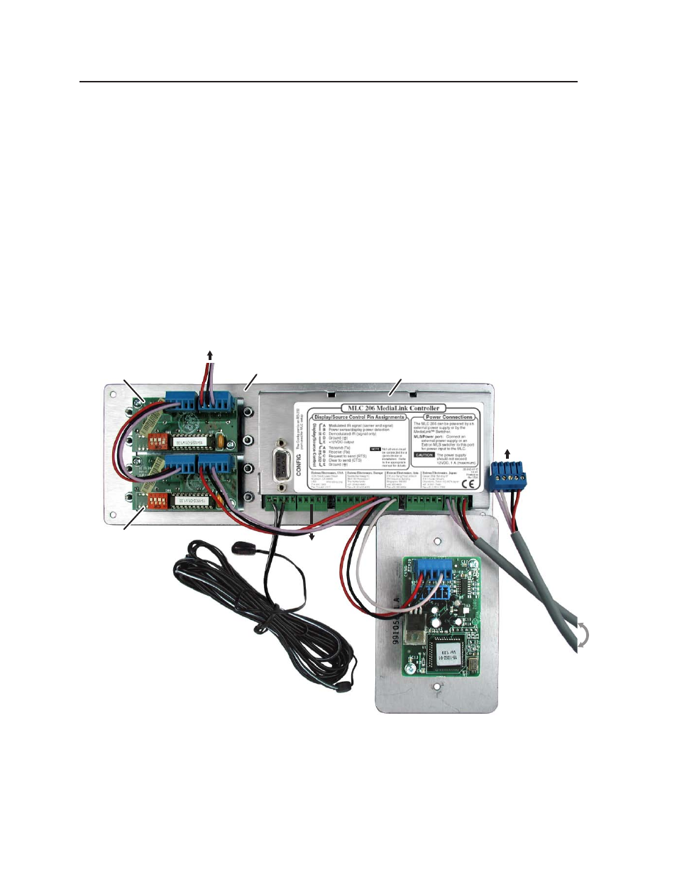
Application diagram
An example of one way to connect accessories to the controller is shown in the
photo below. The Config port is not shown with an RS-232 cable attached because
that connection is only required during setup.
This system includes an MLC mounted in an optional faceplate (MLM-LAAP) that
holds two control modules (IRCMs, ACMs,
and/or RCMs), and an additional
control module is connected to the upper IRCM and mounted in another location.
An IR Link infrared repeater shares the IR/RCM port with the control modules (a
much longer cable than the one shown here would be used). IR Emitters are
connected to the MLC for controlling a VCR, DVD player, tape player or other
source device, and/or projector. An RS-232 connection to the projector could be
made from the adjacent RS-232 Display/Source Control port. Note the wiring on
both ends of the cable that connects the MLC’s MLS/Power port to an MediaLink
Switcher (MLS).
To 1–2 additional
IR Control Modules
(IRCMs)
IR Link Infrared Repeater
rear view
IR Emitter
(Connect 1 per
each IRCM.)
IRCM #1
rear view
MLC 206 rear view
IRCM #2
rear view
To an
MLS
switcher
RS-232
projector
connection
MLM faceplate
Mounting the MLC
Once the system has been cabled, configured (see chapter four), and tested, the
controller can be installed in the wall, furniture, equipment rack, or Euro Channel.