Extron switcher control connections, Extron switcher control connections -10, Installation, cont’d – Extron Electronics MLC 206 AAP EC User Guide User Manual
Page 18: Connecting an mlc 206 to a medialink switcher
Installation, cont’d
MediaLink Controllers • Installation
2-10
Extron switcher control connections
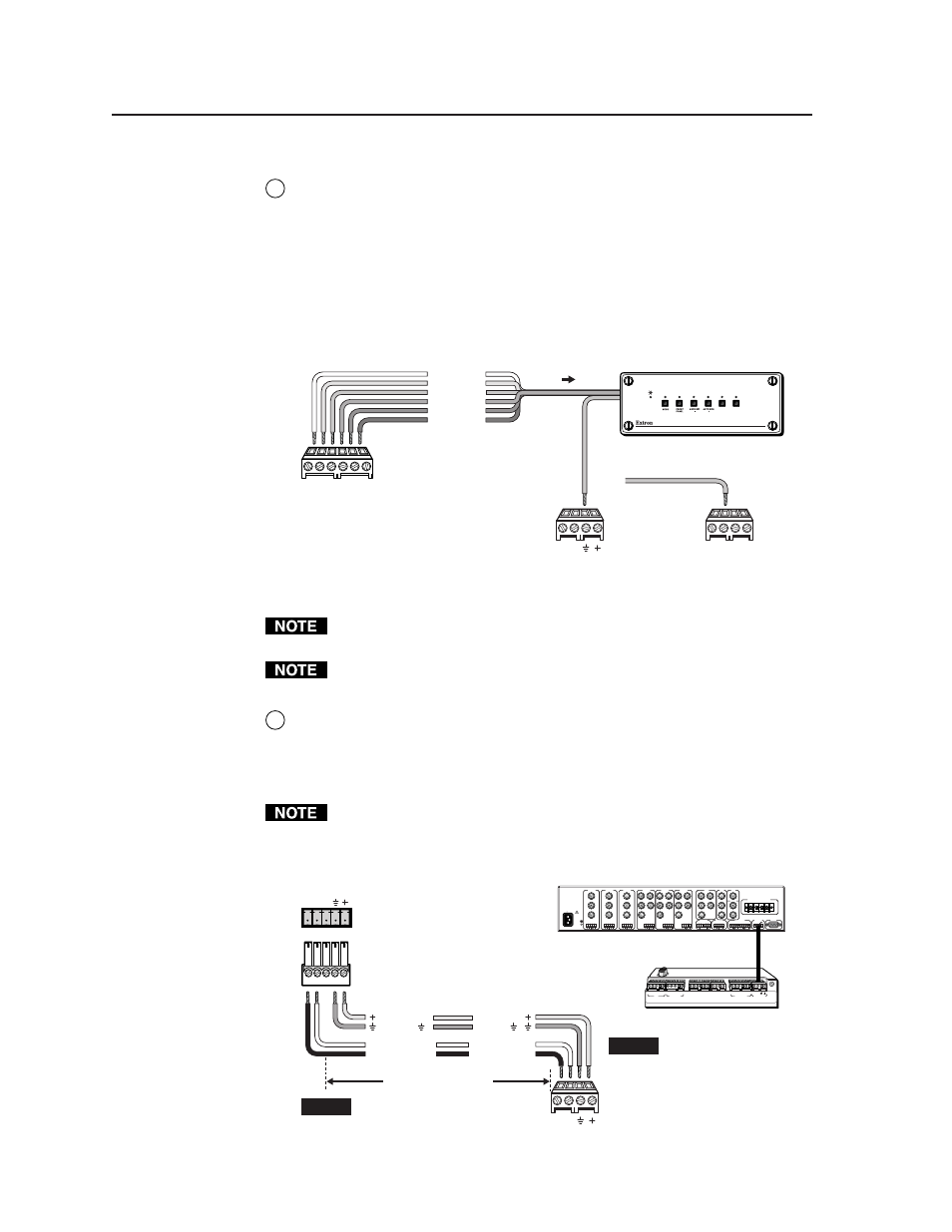
6
Contact closure Tally Out(put) connector
— To effectively add more A/V
inputs to a projector, you aren’t limited to using a MediaLink switcher. If
desired, attach an Extron switcher that accepts contact closure control to this
3.5 mm, 6 pole direct insertion captive screw connector. Each pin corresponds
to a switcher front panel button. When a tally pin is selected, the pin changes
from a high (5V) to a low (0V) state. This momentary high-to-low change can
be used to trigger switching on various contact closure controllable Extron
switchers.
Wire the connector as shown here.
MLC 206 Contact Closure Control
1
6
2 3 4 5
Tally Out
MLC
MLS/Power
port
A B
MLS / Power
MLC
IR / IRCM
port
A B C D
IR / RCM
or
Input 2
Input 1
Input 3
Input 4
Input 5
Input 6
To any
contact closure-
controllable
Extron switcher
6
5
4
3
2
1
SW 6 AR MX
1
2
3
4
5
6
Connect the switcher's
contact closure
ground pin to a
ground on the MLC.
You must connect the ground pin of the switcher’s connector to a ground
connection on the MLC.
Only Extron switchers can be slaved to the MLC via this tally output contact
closure connector.
7
MLS/Power connector
— Connect a cable between this 3.5 mm, 4-pole direct
insertion captive screw connector and an optional Extron MLS switcher for
RS-232 control of the switcher and to provide power from the switcher to the
MLC. See the following diagram. With Extron Comm-Link cable, the
switcher and controller can be up to 250 feet (76.2 m) apart.
The commands issued from this port are standard Extron SIS™ commands,
and they follow the Extron switcher protocol (9600 baud rate, 8-bit, 1 stop bit,
no parity). The commands sent via the MLS/Power connector are fixed and
cannot be altered. See page 3-3 for additional details.
MLC/IR
A B C
MLS 506MA Rear Panel
Connecting an MLC 206 to a MediaLink Switcher
100-240V 0.2A 50/60 Hz
.5A MAX
INPUT 1
VIDEO
Y
C
R-Y
B-Y
YUV
Y
R-Y
B-Y
VIDEO
S-VIDEO
Y
C
INPUT 2
VIDEO
Y
C
R-Y
B-Y
INPUT 3
VIDEO
Y
C
R-Y
B-Y
INPUT 4
R
H/
HV
G
V
B
INPUT 5
R
H/
HV
G
V
B
INPUT 6
R
H/
HV
G
V
B
RGB
R
H/
HV
G
V
B
4 ohm
MONO AMPLIFIED OUTPUT
COMM
8 ohm
70V
L
R
L
R
L
R
L
R
AUX/MIX
EFFECTS
L
R
SEND
L
R
RETURN
MLC/IR
RS232
CONTACT CLOSURE
A B C
AUDIO OUT
FIXED
VARIABLE
L
R
L
R
L
L
R
R
L
R
MediaLink
Switcher
rear panel
MLC/IR port
NOTE
The switcher provides
power to the controller.
MLC
MLS/Power
port
NOTE
If you use cable that has a
drain wire, tie the drain wire
to ground at both ends.
A B C D E
A B C
IR
Display/Source Control
Extron Switcher Control
Relays
IR / RCM
RS-232
D E
A B C
A B
D
1A 1B 2A 2B 3A 3B
1 2 3 4 5 6
Tally Out
MLS/Power
33-644-01 A
07 01
Pr
inted in the
USA
Ground ( )
+12VDC
Transmit (Tx)
B
Receive (Rx)
A
250 feet (76.2 m) maximum
A B
MLS / Power
Transmit (Tx)
Receive (Rx)
+12VDC
Ground ( )
B
A
MLC 206 Bottom Panel