Templates – Extron Electronics MLC 206 AAP EC User Guide User Manual
Page 67
B-3
MediaLink Controllers • Dimensions, Templates, Replacements, and Upgrades
Installation
Cable
Cable
Clamp
Wall Stud
Foil
Shield
Screws or Nails
Screw
Braided
Shield
Templates
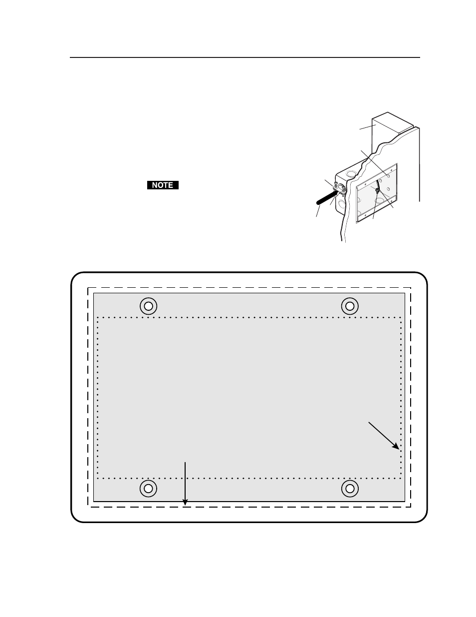
Use the full size template below (MLC 206) or on the next page (MLC 206 AAP) or
a 100% size photocopy of the template as a guide for cutting
a hole in a wall or furniture for installing the MLC. Cut
out the appropriate dashed or dotted inner rectangle of
the template, lay the template against the installation
surface (wall/furniture), and mark the opening on
the surface.
The controller requires a depth of at least 1.25”
(3.2 cm) inside the wall or furniture.
If you use a wall box or mud ring,
connect it to an earth ground. If you
do not use a grounded wall box or
mud ring, ground the faceplate to an
earth ground, or tie it to the circuit
ground via a ground pin on the
circuit board.
The light gray area represents the layout of the
electrical box (3.75"H x 5.6"W) against
the rear of the front panel.
The dashed line indicates the cut-out area
(3.95"H x 5.8"W) for installing
the electrical wall box.
To install the controller
without
a wall box,
use the cut-out area (2.9"H)
indicated by the dotted line.