Connecting an mlc 206 to an external power supply – Extron Electronics MLC 206 AAP EC User Guide User Manual
Page 19
2-11
MediaLink Controllers • Installation
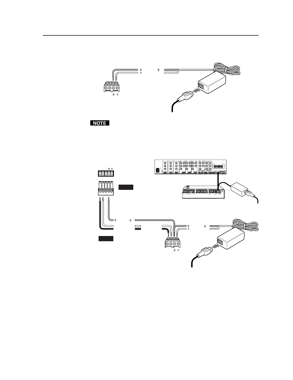
If you are not using an optional switcher, connect an external power supply
(12VDC, 1 A maximum) to this port to power the MLC as shown in the
following diagram.
Connecting an MLC 206
to an external power supply
MLC
MLS/Power
port
A B
MLS / Power
Ground ( )
+12VDC input
Ground all devices
An external
power supply
(12VDC, 1A max.)
Check the power supply’s polarity before connecting it to the MLC.
If you choose to power the MLC from a separate external power supply rather
than from a MLS 306/506/506 MA/506 SA or MLS 100 Series switcher, you
must
connect a ground wire between the MLS and the MLC, as shown in the
following diagrams.
Ground ( )
+12VDC input
MLC/IR
A B C
MLS 506MA Rear Panel
Connecting an MLC 206
to a MediaLink Switcher and
an external power supply
100-240V 0.2A 50/60 Hz
.5A MAX
INPUT 1
VIDEO
Y
C
R-Y
B-Y
YUV
Y
R-Y
B-Y
VIDEO
S-VIDEO
Y
C
INPUT 2
VIDEO
Y
C
R-Y
B-Y
INPUT 3
VIDEO
Y
C
R-Y
B-Y
INPUT 4
R
H/
HV
G
V
B
INPUT 5
R
H/
HV
G
V
B
INPUT 6
R
H/
HV
G
V
B
RGB
R
H/
HV
G
V
B
4 ohm
MONO AMPLIFIED OUTPUT
COMM
8 ohm
70V
L
R
L
R
L
R
L
R
AUX/MIX
EFFECTS
L
R
SEND
L
R
RETURN
MLC/IR
RS232
CONTACT CLOSURE
A B C
AUDIO OUT
FIXED
VARIABLE
L
R
L
R
L
L
R
R
L
R
MediaLink
Switcher
rear panel
MLC/IR port
NOTE
If using an external
power supply (instead of
the MLS) to power the
MLC, you must connect
a ground wire between
the MLC and MLS.
MLC
MLS/Power
port
NOTE
If you use cable that has a
drain wire, tie the drain wire
to ground at both ends.
A B C D E
A B C
IR
Display/Source Control
Extron Switcher Control
Relays
IR / RCM
RS-232
D E
A B C
A B
D
1A 1B 2A 2B 3A 3B
1 2 3 4 5 6
Tally Out
MLS/Power
33-644-01 A
07 01
Pr
inted in the
USA
Ground ( )
Transmit (Tx)
B
Receive (Rx)
A
A B
MLS / Power
Transmit (Tx)
Receive (Rx)
B
A
MLC 206 Bottom Panel
Ground all devices
External
Power Supply
(12VDC, 1A max.)
External
Power Supply