Serial communication, cont’d, Medialink controllers • serial communication 4-6 – Extron Electronics MLC 206 AAP EC User Guide User Manual
Page 38
Serial Communication, cont’d
MediaLink Controllers • Serial Communication
4-6
Command/response table for special function SIS commands, continued
Command
ASCII Command Response
X?
values
(host to MLC)
(MLC to host)
and additional descriptions
MediaLink Controller
MLC 206
1
2
3
4
5
6
ON
1
2
Button to
associate the
VCR half (even
address) with
Button to
associate the
DVD half (odd
address) with
A
(A x 16) + (B) =
B
X?
X? will be a decimal
number from
000 to 101.
Audio settings
Audio mute on/off
w/display power
10 *
X?
#
AudMute*
X?
0 = no (audio doesn’t mute when
display power is off or unmute
when display power is on).
1 = yes (default) (audio mutes when
display power is off, audio unmutes
when display power is on).
Example:
10*1#
AudMute*1
Example: set audio to mute when
display powers off.
Limit audio level on power-up
11*
X?
#
VolLimit*
X?
0 = audio off, 1 = 1% of max. level,
2 = 2% of max possible level, ...
up to 100.
50 = default value.
100 = no limit on audio level.
If this feature is enabled, the
maximum initial power-up volume
level will not exceed the level
specified by this command.
Example:
11*28#
VolLimit*028
Example: limit power-up volume
to 28% of maximum volume.
Set volume mode
21 *
X?
#
VolMode*
X?
Select the volume mode:
0 = control projector volume.
1 = control switcher audio volume.
IR-related settings
Send IR/RS-232 commands
12 *
X?
#
IRM0*
X?
0 = no (default).
associated with the currently
1 = yes.
selected input (reselect the
current input channel)
upon display power-up
Disable IR commands while
13 *
X?
#
IRM1*
X?
0 = no.
the display’s power is off
1 = yes (default).
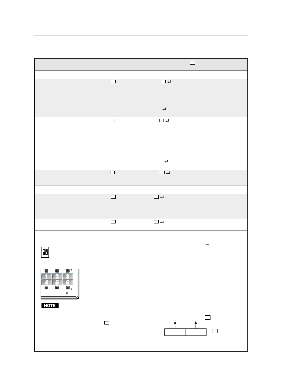
MLC input selection button associations (virtual mapping) for an IRCM-DV+
By design an IRCM-DV+ can be assigned paired module addresses (by DIP switch) of either 1&2 or 3&4 only. It cannot
be assigned to addresses 2&3 or 1&4. The odd-numbered module address (1 or 3) is reserved for DVD control, the
even-numbered module address (2 or 4) is for VCR control. The address DIP switches must be set in order for the
MLC to recognize and reserve memory space for the module. Refer to the Control Modules User’s Manual.
To use an optional IRCM-DV+ with an MLC, you’ll need to associate the DVD portion of this module with an MLC
input selection button
, and associate the VCR portion with a different MLC input
selection button
. The appropriate associated MLC button must be selected (pressed) in order
to activate and use the VCR portion or the DVD portion. You cannot activate both parts
(VCR and DVD) at the same time. If you do not associate (map) the IRCM-DV+’s addresses
(1&2 or 3&4) with MLC buttons, you cannot activate and use either the DVD or the VCR part
of the IRCM-DV+.
You cannot assign both the DVD and VCR portions to the same MLC input selection button.
If two IRCM-DV+ modules are connected to the MLC, each addresses (1, 2, 3, 4)
should be assigned to a different MLC button.
Here’s how to determine the value of
X?
for the following commands:
(continued)