Rear/bottom panel cable connections, Display (projector) and source control connections, Rear/bottom panel cable connections -6 – Extron Electronics MLC 206 AAP EC User Guide User Manual
Page 14: Installation, cont’d
Installation, cont’d
MediaLink Controllers • Installation
2-6
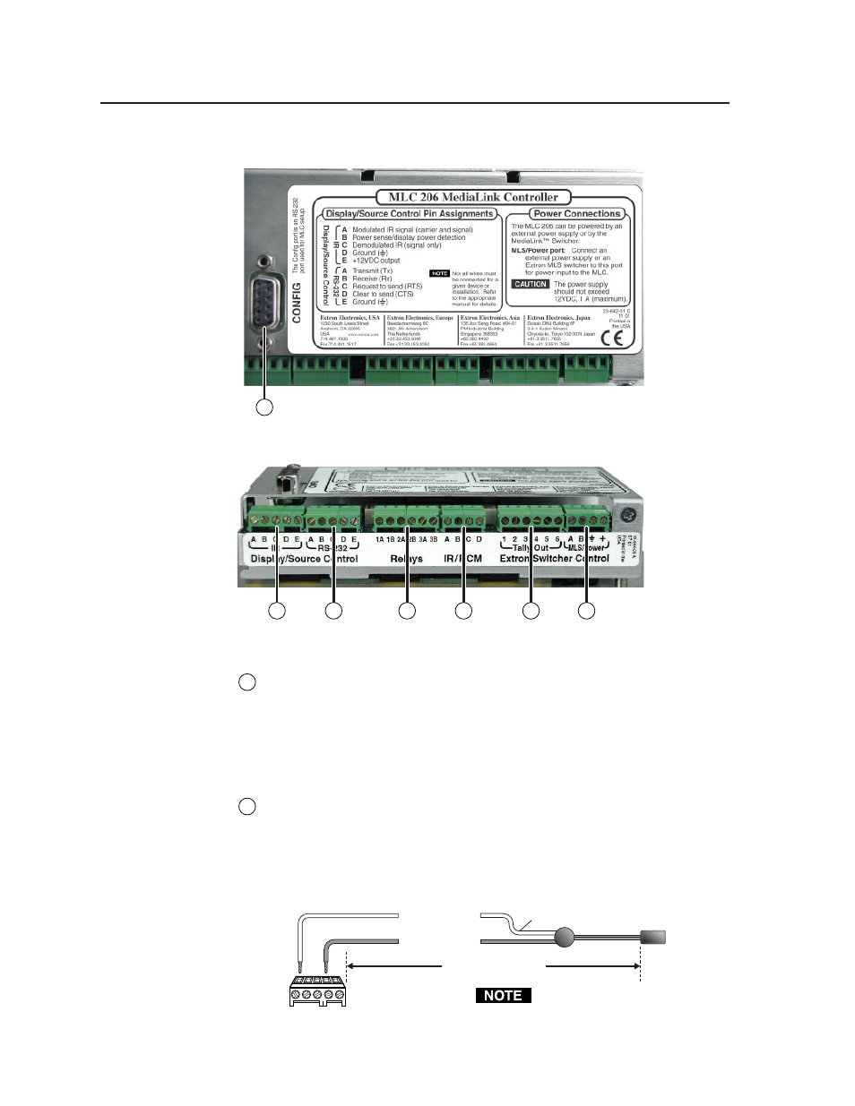
Rear/bottom panel cable connections
MLC 206 rear view
MLC 206 bottom view
1
Configuration port
— This port is used for system configuration and for
loading control files into the MLC. Connect a host computer, third party
control system, or a terminal such as a personal digital assistant to the MLC
via this rear panel 9-pin HD female RS-232 connector. Commands and drivers
can be downloaded into or uploaded from the MLC via this port. See chapter
four for details about the setup software and downloading drivers.
Display (projector) and source control connections
2
IR Display/Source Control connector
— Infrared control signals are sent to
A/V devices via accessories connected to this port. Connect Extron
IR Emitters or an IR Broadcaster to this 3.5 mm, 5-pole direct insertion captive
screw connector so display and/or source devices can be controlled via
infrared commands from the MLC. Up to four IR Emitters can be connected
to the MLC via this connector at one time. Wire the connector as shown in the
following illustrations.
MLC
IR control
port
For the IR Emitter only
IR
Emitter
White striped wire only
A B C D E
IR
Modulated IR
Ground
110 feet (33.5 m) maximum
Connect
up to 4 IR
Emitters
(max.).
D
A
1
3
4
2
6
7
5
Place the head of each IR Emitter
over or directly adjacent to the
controlled device’s IR receiver.