Command/response table for advanced instructions, Based control program) -8, Serial communication, cont’d – Extron Electronics MLC 206 AAP EC User Guide User Manual
Page 40
Serial Communication, cont’d
MediaLink Controllers • Serial Communication
4-8
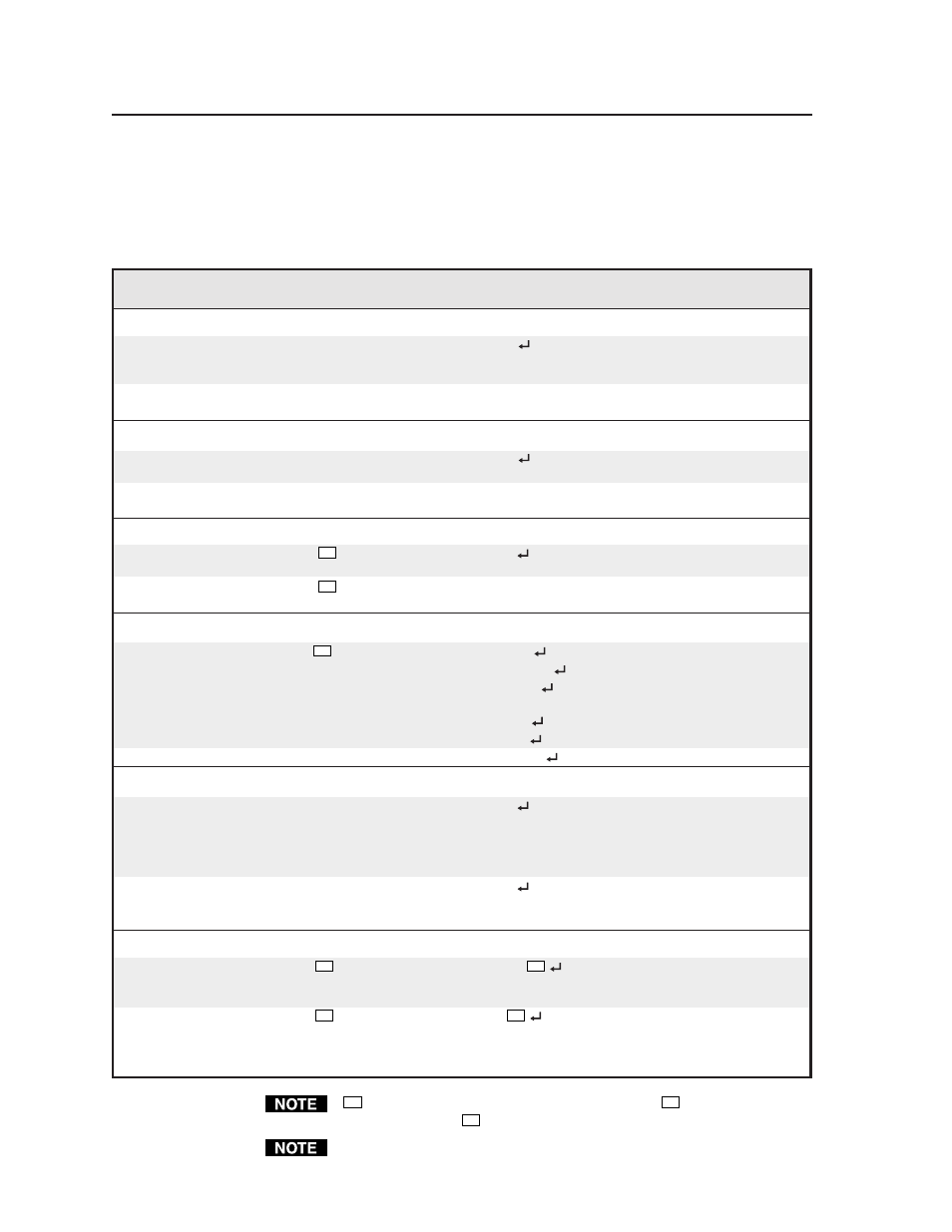
Command
Hex. command
Response
Additional description
(host to MLC)
(MLC to host)
Send/receive data to/from page 0 memory
Send
80 A0 [16k bytes of data]
Dnl0
The host downloads 16k bytes
of binary data to page 0 of the
MLC’s memory.
Receive
80 A1
The MLC sends 16k bytes of
binary data to the host.
Send/receive data to/from page 1 memory
Send
80 A2 [16k bytes of data]
Dnl1
The host downloads 16k bytes of binary
data to page 1 of the MLC’s memory.
Receive
80 A3
The MLC sends 16k bytes of
binary data to the host.
Send/receive a segment (256 bytes) of data (a segment relating to a single button)
Send
80 A6
??
[256 bytes of data]
Seg0
The host sends 256 bytes of
binary data to the MLC.
Receive
80 A7
??
The MLC sends 256 bytes of
binary data to the host.
Initiate or abort IR learning
Learn ready
80 B0
??
LrnRdy
Initiate IR learning.
LrnTimOut
Timeout during IR learning.
LrnRetry
Retry IR learning.
(Aim remote
control at MLC, press button again.)
LrnFail
IR learning has failed.
LrnOK
IR learning has succeeded.
Abort learning
80 B1
Lrn Abort
Abort IR learning.
Set pass-through/normal mode
Set to pass-through mode
80 C0
Hst1
Set the MLC to RS-232 pass-
through mode. RS-232 commands
will go directly to a connected
Extron MLS switcher for direct
control of switcher settings.
Set to normal mode
80 C1
Hst0
Set/reset the MLC to normal
mode. RS-232 commands are
processed by the MLC.
Activate a memory block (segment)/emulate a button press
Activate a block
80 D0
??
IRSnd*
??d
Activate/trigger a memory
block. (Send the command
stored at that address).
Emulate a button press
80 D1
??
Btn
??d
Simulate pressing a button.
(Send the command and/or
perform the function [relay
triggering] stored in the block.)
??
indicates the block number in hex notation where
??
can be 0 to 7F (hex)
(0 to 127 decimal).
??d
indicates the block number in ASCII numeric notation.
The responses shown are ASCII.
Command/response table for advanced instructions
(for the Windows-based control program)
Data downloads/uploads are initiated by sending a series of hex commands to the
host RS-232 port of the MLC. The Windows-based control program uses these
commands mainly to load and save driver data and system configuration settings.