Pinout guide, Pinout guide -13, 13 medialink controllers • installation – Extron Electronics MLC 206 AAP EC User Guide User Manual
Page 21
2-13
MediaLink Controllers • Installation
Pinout guide
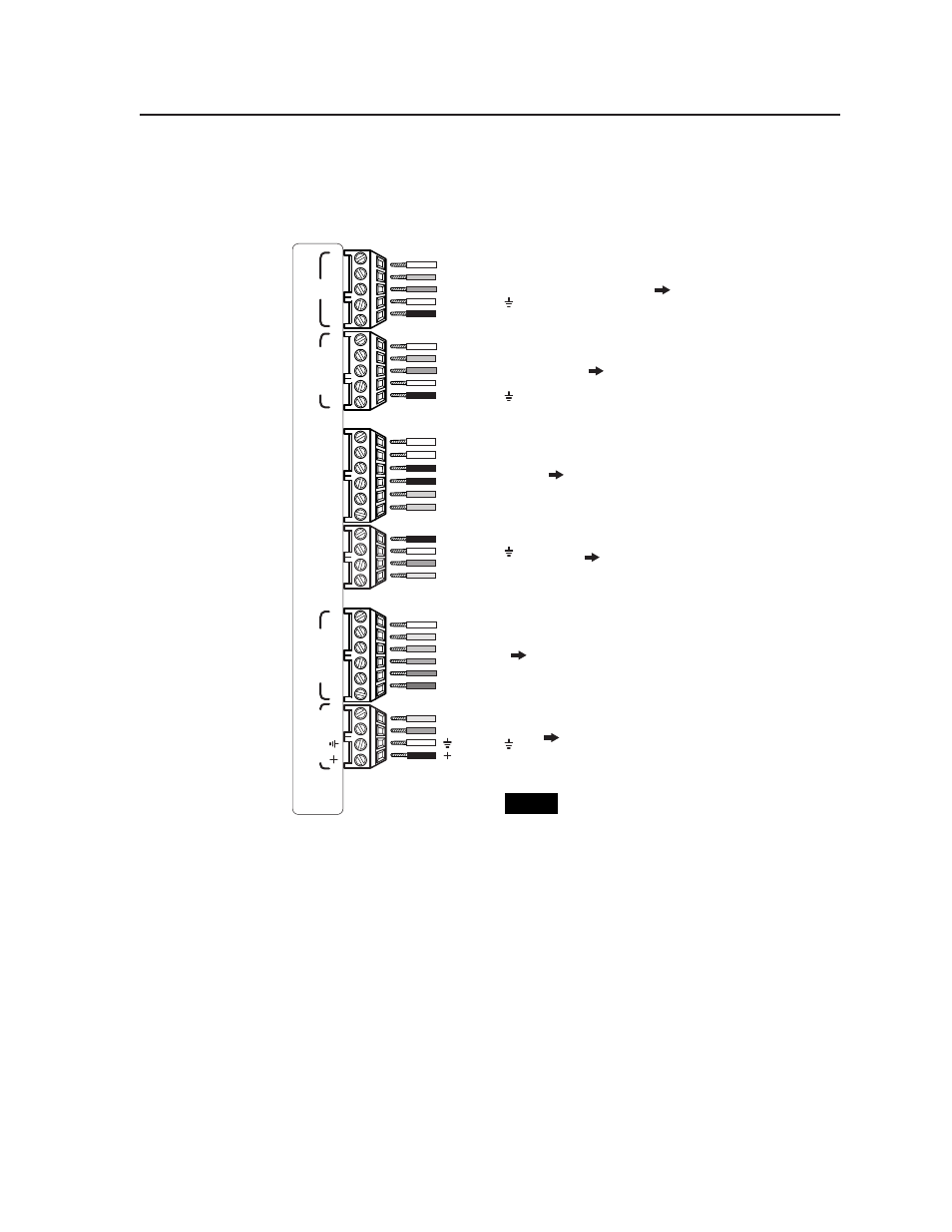
The illustration below summarizes the pin assignments of all of the MLC’s bottom
panel connectors that are covered in detail on pages 2-6 to 2-12.
AB
CD
E
A
B
C
IR
Displa
y/Sour
ce Contr
ol
Extr
on Switc
her Contr
ol
Rela
ys
IR
/RCM
RS-232
DE
A
B
C
A
B
D
1A
1B
2A
2B
3A
3B
123456
T
all
y Out
MLS
/P
o
wer
33-644-01 A
07 01
Printed in the
USA
+12VDC output
Modulated IR signal (carrier & signal)
Power sense/display power detection
Demodulated IR (signal only)
Ground ( )
E
D
C
B
A
Ground ( )
Transmit (Tx)
Receive (Rx)
Request to send (RTS)
Clear to send (CTS)
E
D
C
B
A
Ground ( )
+12VDC input
Receive (Rx)
Transmit (Tx)
B
A
C
Modulated IR (IR Link)
+12VDC output
Control signal (IRCM)
Ground ( )
D
B
A
Input 2
Input 1
Input 3
Input 4
Input 5
Input 6
6
5
4
3
2
1
Relay 1, pin B
Relay 1, pin A
Relay 2, pin A
Relay 2, pin B
Relay 3, pin A
Relay 3, pin B
1A
3B
1B
2A
2B
3A
To the
display/projector's
RS-232 port
To an IR Link
and/or MediaLink
Control Module(s)
To any contact closure-
controllable Extron switcher
To/from
room control
equipment
To/from a MediaLink Switcher
or
an external 12VDC, 1A power supply
To IR Emitter(s),
an IR Broadcaster,
the projector's wired
remote port, and/or a
Display Power Sensor
MediaLink Controller (MLC 206) bottom panel connector pinouts
NOTE
Not all wires must be connected for a
given device or installation. Refer to
the appropriate manual for details.