Installing a firmware upgrade, Extron ism 482, Switcher – Extron Electronics ISM 482 User Manual
Page 72
ISM 482 Integrated Scaling Matrix Switcher • Maintenance and Modifications
66
10.
Replace the top cover on the ISM.
11.
Fasten the top cover with the screws that were removed in step 3 and step 4.
12.
Rack mount the switcher if desired and reconnect all cables.
Installing a Firmware Upgrade
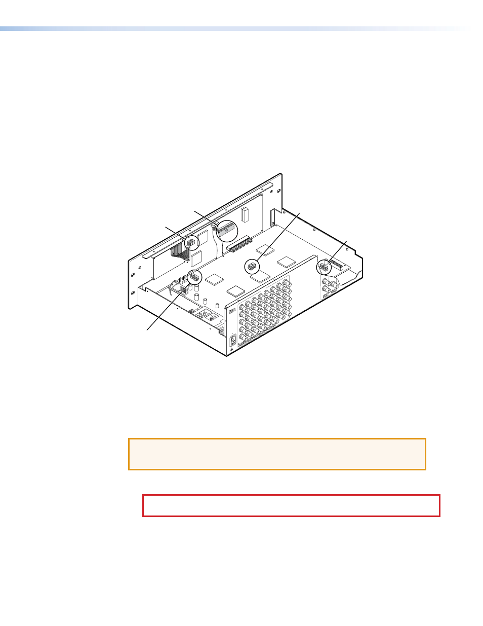
In some cases the ISM firmware may require replacement with an updated version. There
are nine user-replaceable firmware chips (see figure 50): U1, U2, and U6 on the front panel
circuit board and U98, U99, U100, U101, U102, and U103 on the main circuit board. The
U-numbers are printed on the circuit boards. Extron recommends that you send the unit in
to Extron for service and updates.
1
2
3
4
5
6
7
8
100
- 24
0
50/6
0 H
z
1.2A MAX.
R
1
G
B
H/H
V
R
2
G
B
H/H
V
R
3
G
B
H/H
V
R
INP
UT
S
4
G
B
H/H
V
R
5
G
B
H/H
V
R
6
G
B
H/H
V
R
7
G
B
H/H
V
R
8
G
B
H/H
V
B
H/H
V
V
H/H
V
V
Extron
ISM 482
Switcher
U1
U2
U100
U101
U6
U102
U103
U98
U99
Figure 50.
ISM Firmware Chip Locations
•
Chips U1 and U2 are replaced as a pair.
•
Chip U6 is replaced alone.
•
Chips U98, U99, U100, and U101 are replaced as a set.
•
Chips U102 and U103 are replaced as a pair.
ATTENTION: Changes to firmware must be performed by authorized service
personnel only. Some ISM firmware updates must be performed at the Extron
factory.
Replace firmware in the ISM as follows:
CAUTION: Electric shock hazard. To prevent electric shock, always unplug the
ISS from the AC power source before opening the enclosure.
1.
Opening and Closing the Switcher
2.
Locate the firmware chips to be replaced on the main or front panel circuit board (see
figure 50).
3.
After you are electrically grounded, use a DIP chip puller to grasp each IC chip and pull
it out of the sockets.