Cabling and rear panel views, Input connections, Figure 2. mounting the switcher – Extron Electronics ISM 482 User Manual
Page 12: Figure 3. ism 482 rear panel connectors, Int eg ra tio n s ca lin g m at rix
ISM 482 Integrated Scaling Matrix Switcher • Installation
6
BLA
CK
1
2
3
4
5
6
7
8
VIDE
O
1
2
OUTPU
T
1
2
3
4
5
6
7
8
AU
DIO
MUTE
COLOR
/
TINT
BR
T/
CONT
SIZE
CENTER
FIL
TER
ADJUS
T
MENU
NEXT
INPUTS
ISM 482
INT
EG
RA
TIO
N S
CA
LIN
G M
AT
RIX
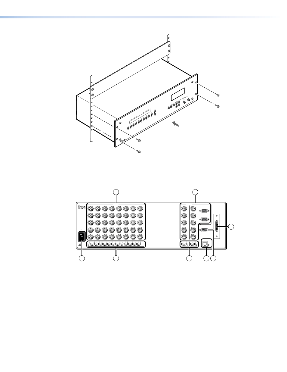
Figure 2.
Mounting the Switcher
Cabling and Rear Panel Views
All connectors are on the rear panel (see figure 3).
100- 240
50/60 Hz
1.2A MAX.
1
2
H/HV
V
3
H/HV
V
INPUTS
4
H/HV
V
5
H/HV
V
6
H/HV
V
7
H/HV
V
R/R-Y
8
G/Y
VID
B/C
B-Y
R/R-Y
G/Y
VID
B/C
B-Y
R/R-Y
G/Y
VID
B/C
B-Y
R/R-Y
G/Y
VID
B/C
B-Y
R/R-Y
G/Y
VID
B/C
B-Y
R/R-Y
G/Y
VID
B/C
B-Y
R/R-Y
G/Y
VID
B/C
B-Y
R/R-Y
G/Y
VID
B/C
B-Y
H/HV
V
1
OUTPUTS
1
2
RS-232
2
2
3
4
5
6
7
8
H/HV
V
1
R
G
B
H/HV
V
R
G
B
H/HV
V
ETHERNET
LINK
ACT
DVI OUT
1
3
5
7
2
4
8
6
Figure 3.
ISM 482 Rear Panel Connectors
Input Connections
a
AC power connector — Plug a standard IEC power cord into this connector to
connect the switcher to a 100 to 240 VAC, 50 Hz or 60 Hz power source.
b
Input video connectors — Connect computer or RGB video, component
video, S-video, or composite video sources to these female BNC connectors.
Figure 4 on the next page shows how to connect the various video formats.