Extron ism 482, Switcher – Extron Electronics ISM 482 User Manual
Page 71
ISM 482 Integrated Scaling Matrix Switcher • Maintenance and Modifications
65
1
2
3
4
5
6
7
8
100
- 24
0
50/6
0 H
z
1.2A MAX.
R
1
G
B
H/H
V
R
2
G
B
H/H
V
R
3
G
B
H/H
V
R
INP
UT
S
4
G
B
H/H
V
R
5
G
B
H/H
V
R
6
G
B
H/H
V
R
7
G
B
H/H
V
R
8
G
B
H/H
V
B
H/H
V
V
H/H
V
V
Extron
ISM 482
Switcher
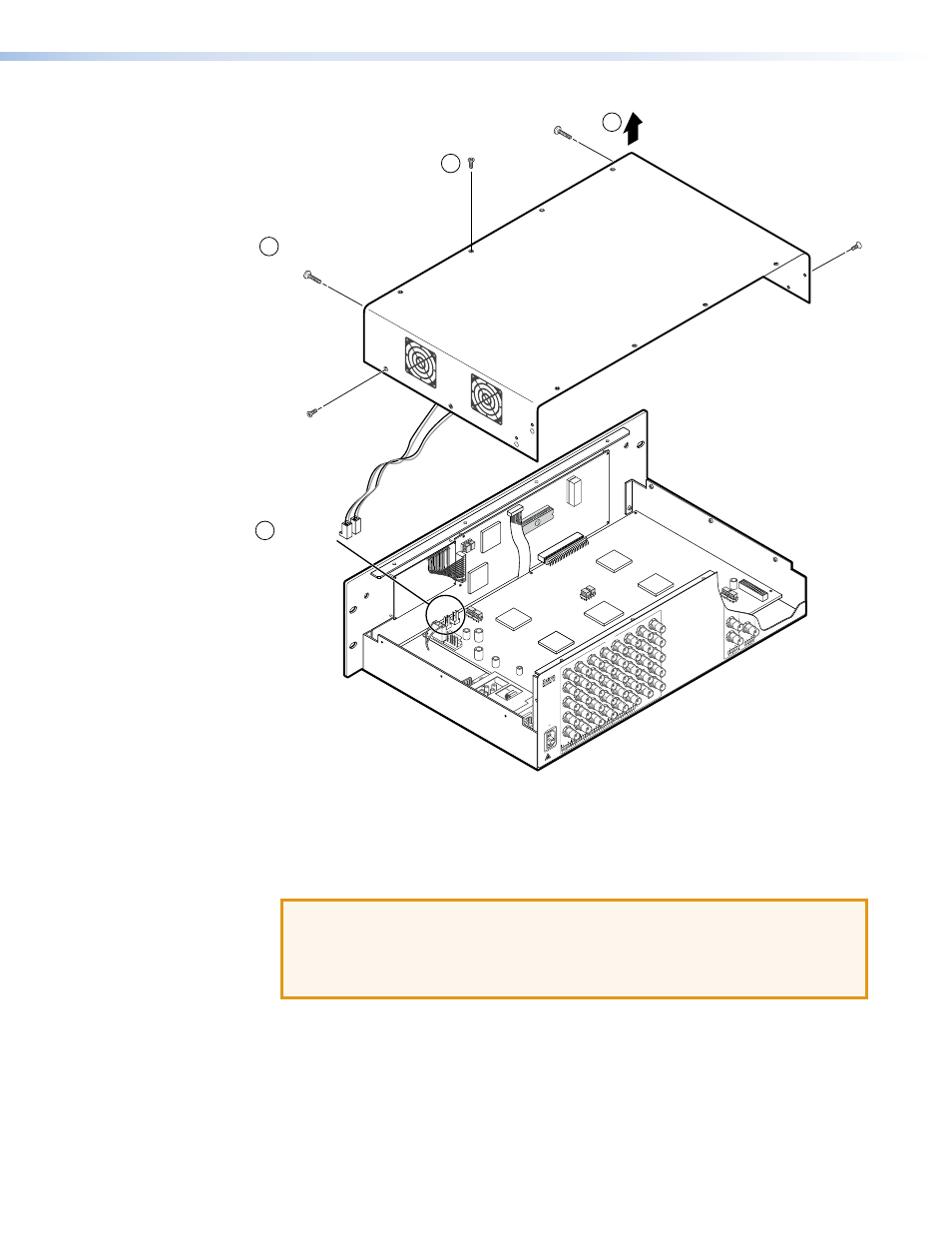
Remove (16)
screws.
Remove top two
front panel screws.
Lift cover straight up.
Disconnect from/
connect to
J8 and J13.
J8
J13
3
4
6
5
Figure 49.
Removing the ISM Cover
4.
Remove the top two front panel screws.
5.
Lift the top cover straight up approximately 5 inches until you can access the fan power
cords.
ATTENTION: Do not touch any switches or other electronic components inside
the ISM. Doing so could damage the switcher. Electrostatic discharge (ESD)
can damage IC chips even though you cannot feel it. You must be electrically
grounded before proceeding with firmware replacement. A grounding wrist strap
is recommended.
6.
Disconnect the two fan power cords from connectors J8 and J13 on the main board.
7.
Lift the top cover out of the way.
8.
Perform the desired maintenance procedure (see “Installing a Firmware Upgrade” on the
next page or
on page 67).
9.
Reconnect the two fan power cords to connectors J8 and J13 on the main board. It
does not matter which fan is connected to which connector.