Ddc/edid resolution area, Video adjustment area, Output configuration area – Extron Electronics FOX 500 DVI Tx User Guide User Manual
Page 35: Remote control, cont’d
FOX 500 Tx/Rx • Remote Control
Remote Control, cont’d
4-20
FOX 500 Tx/Rx • Remote Control
4-21
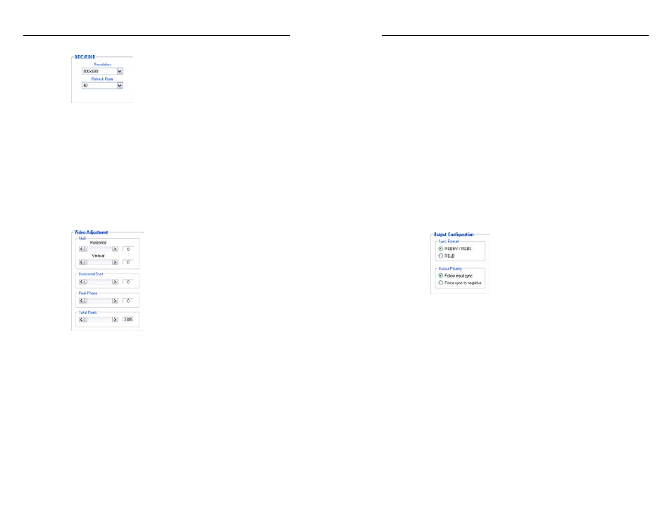
DDC/EDID Resolution area
Figure 4-9 — Extender program DDC/EDID Resolution
area
The DDC/EDID Resolution area provides drop boxes that let
you manually set the DDC Resolution and refresh rate.
N
The transmitter's rear panel DDC Resol(ution) rotary
switch must be in position 1 for the variables to be
changeable via FOX Extender Program. The Resolution
and Refresh Rate drop boxes are grayed out and
unavailable for selection if the switch is in other than
position 1.
Video Adjustment area
Figure 4-10 — Extender program Video Ajustment area
The Video Adjustment area provides slider controls that let you
change the following video parameters:
• Shift Horizontal (position)
• Shift Vertical (position)
• Horizontal Start
• Pixel Phase
• Total Pixels
N
When you make changes to the horizontal start, pixel
phase, or total pixels settings, the value is changed in the
transmitter.
If you are connected to either of the receiver's serial
ports, and the Optical 2 cable is not connected in your
system, you cannot change these values using the
control program. These slider controls are grayed out
(unavailable).
N
When you make horizontal or vertical position changes
(shift the image), the setting is changed in the receiver. It
reports the shift values to the transmitter via the optional
Optical 2 cable.
If you are connected to either of the transmitter's serial
ports, and the Optical 2 cable is not connected in your
system, you can still shift the image in the control
program's Video Adjustment area, but the program
cannot report the position values.
Output Configuration area
Figure 4-11 — Extender program Output
Configuration area
Sync Format radio buttons —
Click either the RGBHV/RGBS
or RGsB radio button to select the desired video output sync
format.
Output Polarity radio buttons —
Click either the Follow input
sync
or Force sync to negative radio button to select the
desired video output sync polarity.
N
When you make output configuration changes, the
setting is changed in the receiver. It reports the changes
to the transmitter via the optional Optical 2 cable.
If you are connected to either of the transmitter's serial
ports, and the Optical 2 cable is not connected in your
system, the program cannot report the output sync
format and polarity position settings in the control
program's Video Adjustment area. You can change
the output sync format and polarity, but the program
cannot report the changes.