Receiver rear panel connections, Receiver rear panel connections -11, If you connect only one fiber optic cable (item – Extron Electronics FOX 500 DVI Tx User Guide User Manual
Page 14: Installation, cont’d
FOX 500 Tx/Rx • Installation
Installation, cont’d
2-10
FOX 500 Tx/Rx • Installation
2-11
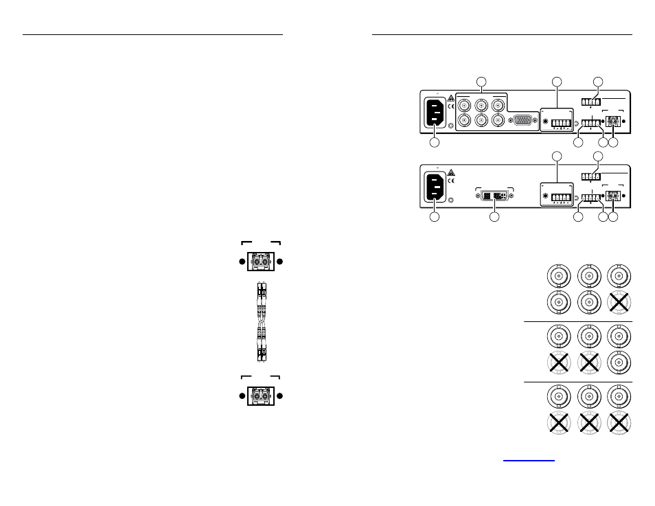
Receiver rear panel connections
All connectors except the Configuration port are on the rear
panel (figure 2-7).
FOX 500 Rx
AUDIO OUTPUTS
RGB OUTPUTS
R
G
B
S
H
V
L
R
RS-232
OVER FIBER
Tx Rx
NA
REMOTE
RS-232
ALARM
OPTICAL
2* 1
*
OPTIONAL FOR
RETURN DATA
LINK
LINK
Tx Rx
1 2
100-240V 0.3A
50/60 Hz
RGB
AUDIO OUTPUTS
L
R
RS-232
OVER FIBER
Tx Rx
NA
REMOTE
RS-232
ALARM
OPTICAL
2* 1
*
OPTIONAL FOR
RETURN DATA
LINK
LINK
Tx Rx
1 2
100-240V 0.3A
50/60 Hz
FOX 500 DVI Rx
DVI - D OUTPUT
FOX 500 Rx
FOX 500 DVI Rx
18
19
16
15
17
12
14
18
13
19
16
15
17
14
Figure 2-7 — FOX 500 Rx receiver’s connectors
l
RGB Outputs connectors (FOX 500 [RGB] only) —
N
Both video
outputs are active.
BNC connectors
— Connect
an RGBHV, RGBS, RGsB,
or RsGsBs video display
to these BNC connectors.
Connect the cables as shown
at right.
15-pin HD connector
—
Connect an analog
VGA - UXGA RGB video
display to this 15-pin HD
female connector.
N
You can set the
receiver to output
the desired video
format, RGBHV,
RGBS, or RGsB.
RGBHV is the
default. See "Format submenu" in "Output
Configuration menu" in chapter 3, "Operation".
j
Fiber optic connectors and LEDs —
W
These units output continuous invisible light,
which may be harmful and dangerous to the eyes;
use with caution. For additional safety, plug the
attached dust caps into the optical transceivers
when the fiber optic cable is unplugged.
N
Ensure that you use the proper fiber cable for your
transmitter/receiver pair. Typically, singlemode fiber has
a yellow jacket and multimode cable has an orange jacket.
N
Only one fiber optic cable, Optical 1, is required for
video, audio, and serial command transmission. But,
if you connect only one fiber optic cable, you will not
receive RS-232 reports from the controlled device, and
there will be reduced front panel, Windows-based
control program, and RS-232 command functionality
on the Rx unit. To receive responses from the controlled
device and for full functionality, you will need to install
both fiber optic cables.
Optical 1
(required) — For all one-way
video, audio, and serial communications
from the transmitter to the receiver,
connect a fiber optic cable to the Optical 1
LC connector.
Connect the free end of this fiber optic
cable to the Optical 1 connector on the
FOX 500 Rx receiver
(item
r
on figure 2-7)
or to any other compatible Extron FOX 500
device
.
Optical 2
(optional) — For all one-way
serial communications from the receiver
to the transmitter, connect a fiber optic
cable to the Optical 2 LC connector.
Connect the free end of this fiber optic
cable to the Optical 2 connector on the
FOX 500 Rx receiver
(item
r
on figure 2-7)
or to any other compatible Extron FOX 500
device
.
Link 1 and Link 2 LEDs
— When lit, the link is active (light
is received).
k
AC power connector — Plug a standard IEC power cord
into this connector to connect the transmitter to a 100 VAC to
240 VAC, 50 or 60 Hz power source.
R
RGBHV
G
B
V
RGBS
RGsB
B
S
R
G
V
R
G
B
H
H
H
S
S
V
OPTICAL
1 2*
*
OPTIONAL FOR
RETURN DATA
LINK
LINK
OPTICAL
2* 1
*
OPTIONAL FOR
RETURN DATA
LINK
LINK
Transmitter
to
Receiver