Installation, cont’d – Extron Electronics FOX 500 DVI Tx User Guide User Manual
Page 15
FOX 500 Tx/Rx • Installation
Installation, cont’d
2-12
FOX 500 Tx/Rx • Installation
2-13
m
DVI-I Output connector (FOX 500 DVI only) — Connect a
N
The FOX 500 DVI outputs only the digital signals on
the D
VI-I Output connector. The analog pins on the
port are not connected.
n
Audio Outputs connectors —
N
Both audio outputs are active.
3.5 mm mini jack —
Plug a stereo mini plug into this connector.
5-pole captive screw connector —
This 5-pole, 3.5 mm captive
screw connector outputs the transmitted, unamplified,
line level audio. Connect audio devices, such as an audio
amplifier or powered speakers.
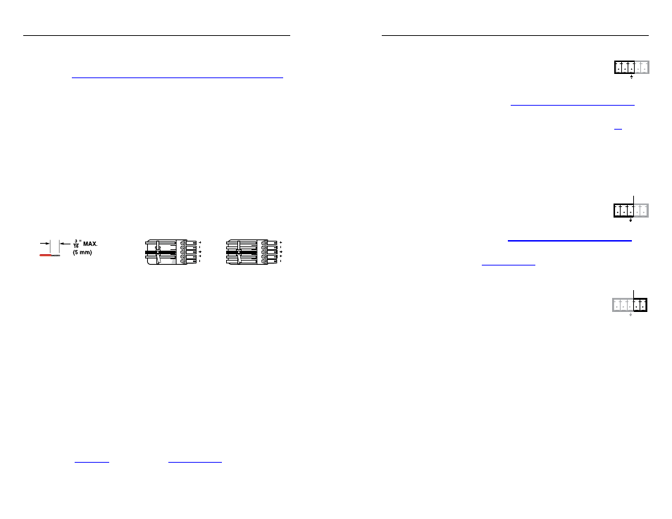
See figure 2-8 to properly wire a captive screw output connector.
Use the supplied tie-wrap to strap the audio cable to the
extended tail of the connector.
Ring
Sleeve(s)
Tip
Tip
Ring
Sleeve(s)
Tip
Tip
Unbalanced Stereo Output
Balanced Stereo Output
NO GROUND HERE.
NO GROUND HERE.
L
R
Do not tin the wires!
Figure 2-8 — Captive screw connector wiring for
stereo audio output
C
Connect the sleeve to ground (Gnd). Connecting
the sleeve to a negative (-) terminal will damage the
audio output circuits.
N
The le
ngth of exposed wires is critical. The ideal
length is 3/16” (5 mm).
•
If the stripped section of wire is longer than 3/16”, the
exposed wires may touch, causing a short circuit.
•
If the stripped section of wire is shorter than 3/16”,
wires can be easily pulled out even if tightly fastened
by the captive screws.
The volume level for the output can be set to either the
consumer line level (-10 dBV) or the professional line level
(+4 dBu) via the front panel or RS-232 control. See chapter 3,
"Operation", and chapter 4, "Remote Control", for details.
o
RS-232 Over Fiber port — If you want the
FOX 500 to pass serial command signals to
the receiver, for serial control of a projector for
example, connect the controlled device to the
receiver via three poles of this 5-pole captive
screw connector. See "Rear panel serial ports connections" on
page
2-16
to wire this connector.
N
If you connect only one fiber optic cable (item
,
on the
next page), you will not receive reports from the controlled
device at the transmitter. To receive responses from the
controlled device, you will need to install two fiber optic
cables.
N
The FOX 500 can pass RS-232 commands and responses
at rates up to 115200 baud.
p
Remote RS-232 port —
For serial control of the
receiver, connect a host device, such as a computer,
touch panel control, or RS-232 capable PDA, to the
transmitter via three poles of this 5-pole captive
screw connector.
See "Rear panel serial ports connections" on
page
2-16
to wire this connector.
See chapter 4, "Remote Control", for definitions of the SIS
commands (serial commands to control the transmitter via this
connector).
q
Alarm outputs port — For remote monitoring of
the status of fiber optic link 1, connect a locally-
constructed or furnished monitoring device to
the receiver via two poles of this 5-pole captive
screw connector. When the receiver does not detect a light
link on fiber cable Optical 1, pin 1 and pin 2 of this port are
shorted together.
REMOTE
RS-232
ALARM
Tx Rx
1 2
RS-232
OVER FIBER
Tx Rx
NA
REMOTE
RS-232
ALARM
Tx Rx
1 2