Bell & Gossett S14333 Technologic 5500 Series ZoneSav Controller User Manual
Page 9
9
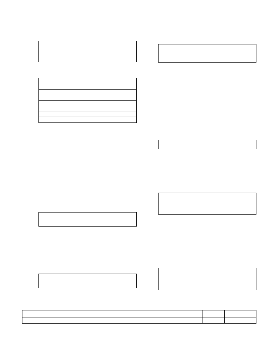
3.1.1.3 Sensor Type
If NO was selected in the Sensor Edit screen, shown
in section 3.1.1.2, the following will be displayed.
Sensor # ##
Type: (Type)
1 = SysT
2 = ZST
3 = ZRT
4 = Flw
5 = Tmp
6 = VFbk
0 = None
Table 4, shown below, gives a description and the
units of each sensor type.
Selection Description
Units
1=SysT
System Temperature
˚F
2=ZST
Zone Supply Temperature
˚F
3=ZRT
Zone Return Temperature
˚F
4=Flw
*Flow GPM
5=Temp
Temperature (for display only)
°F
6=VFbk
Valve Feedback (for display only)
%
0=None
No Sensor
N/A
Table 4: Sensor Types
Enter the numeric key corresponding to the type of
sensor you are setting up. The abbreviation for the
sensor type will appear in the upper right corner of
the display in the following screens. The ZoneSav
controller does not allow more than one sensor to
have types 1, 2, 3, 5, or 6.
*Note: A total of three flowmeters can be set up. The
smallest analog input number that has type "Flw" will
be the Zone Flow. It will be used for flow limit opera-
tion. See section 3.3.4 to set up a flow limit. The
other two flows will not be used in control algorithms.
They are for display only.
3.1.1.4 Sensor Span
After entering the sensor type in section 3.1.1.3, the
display will prompt the user for the sensor span as
shown below.
Sensor No ##
Type: (Type)
Span = #####
Enter the span by pressing the appropriate numeric
keys and ENTER. Obtain the span of the sensor from
the nameplate on the sensor. The span is the numeric
value that corresponds to a 20mA signal.
3.1.1.5 Sensor Zero
After entering the sensor span in section 3.1.1.4, the
display will prompt the user for the zero of the sensor
as shown below.
Sensor No ##
Type: (Type)
Span = #####
Zero = #####
Enter the desired zero value by pressing the appro-
priate numeric keys and ENTER. The Zero corre-
sponds to the numeric value of the sensor at 4mA.
3.1.1.6 Sensor Override
After entering the sensor zero in section 3.1.1.5, the
display will prompt the user for Override (Yes/No) as
shown below.
Sensor No ##
Type: (Type)
Span = #
Zero = #
Override: Y/N
The controller is capable of accepting sensor input
either through a 4-20mA analog input or through the
communication port. See section 3.3.10 for available
protocols. The communication port must be set up
properly and connected to an external building
automation system (BAS).
Press YES and ENTER to receive the sensor signals
via the communication port. Press NO and ENTER to
receive the sensor signals via the analog input card.
After the selection is made, the controller will return
to the Sensor Edit screen shown in section 3.1.1.2.
3.1.1.7 Do Another
If YES was selected in the Sensor Edit screen, shown
in section 3.1.1.2, the display will show the following.
DO ANOTHER ? (Y/N)
Press YES and ENTER to set up another sensor, or
press NO and ENTER to return to the Sensor Setup
screen shown in section 3.1.
3.1.2
Sensor Log Rate
From the Sensor Setup screen, shown in section 3.1,
Press 2 and ENTER to get to the Sensor Log Rate
screen shown below.
Sensor Log Rate: #
0=None
2=Hr
4=Week
1=Min
3=Day
5=Month
OK ? (Y/N)
Press YES and ENTER to accept the current Sensor
Log Rate, or press NO and ENTER to edit the Sensor
Log Rate. See section 4.7.5 for more information on
the Data Log. See Table 5 for a description of the
Sensor Log Rate.
3.2
Valve Setup
From the Setup Selection screen, shown in section 3,
press 2 and ENTER to get to the Valve Setup screen
shown below.
SELECTION: # 0 = EXIT
1 = Valve Pos. Limit
2 = Valve Log Rate
3 = Valve Signal
Push the numeric key corresponding to the desired
Valve Setup submenu, and press ENTER to proceed.
Variable
Description
Default Value
Range
Field Value
Sensor Log Rate
One data point is taken at the end of the interval
0
0-5
Table 5: Sensor Log Rate Variable