Bell & Gossett S14333 Technologic 5500 Series ZoneSav Controller User Manual
Page 16
16
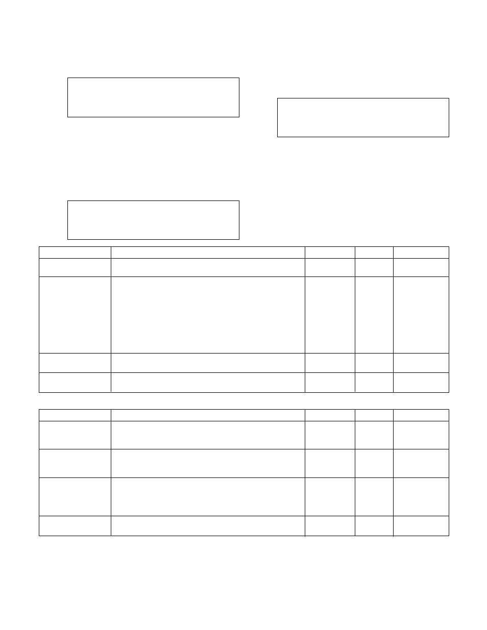
3.3.9.3 AO
From the I/O Setup Menu, shown in section 3.3.9,
press 3 and ENTER to get to the AO screen shown
below.
Total Avail. AO = #
Opt. AO = #
Code = #
(Functionality)
Exit: ? (Y/N)
To return to the I/O Setup Menu, shown in section
3.3.9, press YES and ENTER. To edit the fields,
press NO and ENTER. See Table 23 for a description
of the AO variables.
3.3.10
Communication Setup
From the System Setup screen, shown in section 3.3,
press 10 and ENTER to get to the Communication
Setup screen shown below.
Comm. Setting
1 = BACnet
2 = JC N2
3 = Modbus
4 = BACnet/IP
0 = Exit
Select: #
Press the numeric key corresponding to the desired
Communication Setup sub-menu, and press ENTER.
3.3.10.1 BACnet
From the Communication Setup screen, shown in
section 3.3.10, press 1 and ENTER to get to the
BACnet screen shown below.
BACnet MS/TP
Baud, 8, 1, 1, N Slave
MAC = ###
Inst = ####
SP Ovrd: ? Y/N
Exit ? Y/N
The first line confirms setup for the BACnet protocol.
The second line defines the baud rate, 8 bit data
packets, 1 stop bit, 1 start bit and no parity. The
ZoneSav Controller is a slave device only. To return
to the Communication Setup Menu, shown in section
3.3.10, press YES and ENTER. To edit the fields,
press NO and ENTER. Table 24 gives a description
of the BACnet variables.
Variable
Description
Default Value
Range
Field Value
Total Available AOs
This screen can not be modified. It is here to advise the
N/A
0-8
user of how many analog outputs can be customized
Opt. AO
Enter the output to be configured as it appears on the
N/A
0-8
wiring diagram. The analog output card can be configured
for 0-10VDC or 4-20mA signals. Remove the card from
the rack. There are two switches below the pin
connector on the back of the card. The bottom switch
#1 configures the first analog output. The top switch #2
configures the second analog output. Select position U
for 0-10VDC and position I for 4-20mA output signals.
Code
Defines the desired functionality of the output. Valid
0
0-9
codes are defined in Appendix C of this manual
Functionality
This message will show the functionality of the code
N/A
N/A
that was entered
Table 23: AO Variables
Variable
Description
Default Value
Range
Field Value
Baud
The baud rate is user adjustable
9600
9600,
19200,
38400
MAC Address
Obtain the node number from the manufacturer that
128
1-255
supplied the device that will communicate with the
Technologic Controller
Inst
Unique instance numbers are needed only if multiple
100
0-9999
TECHNOLOGIC panels are connected to the same
network. Some BACnet devices do not require this
number to communicate with the ZonSav controller
SP Ovrd
Select “Y” to allow the setpoints to be overwritten
N
Y/N
through the communications port
Table 24: BACnet Variables