Bell & Gossett S14333 Technologic 5500 Series ZoneSav Controller User Manual
Page 10
10
3.2.1
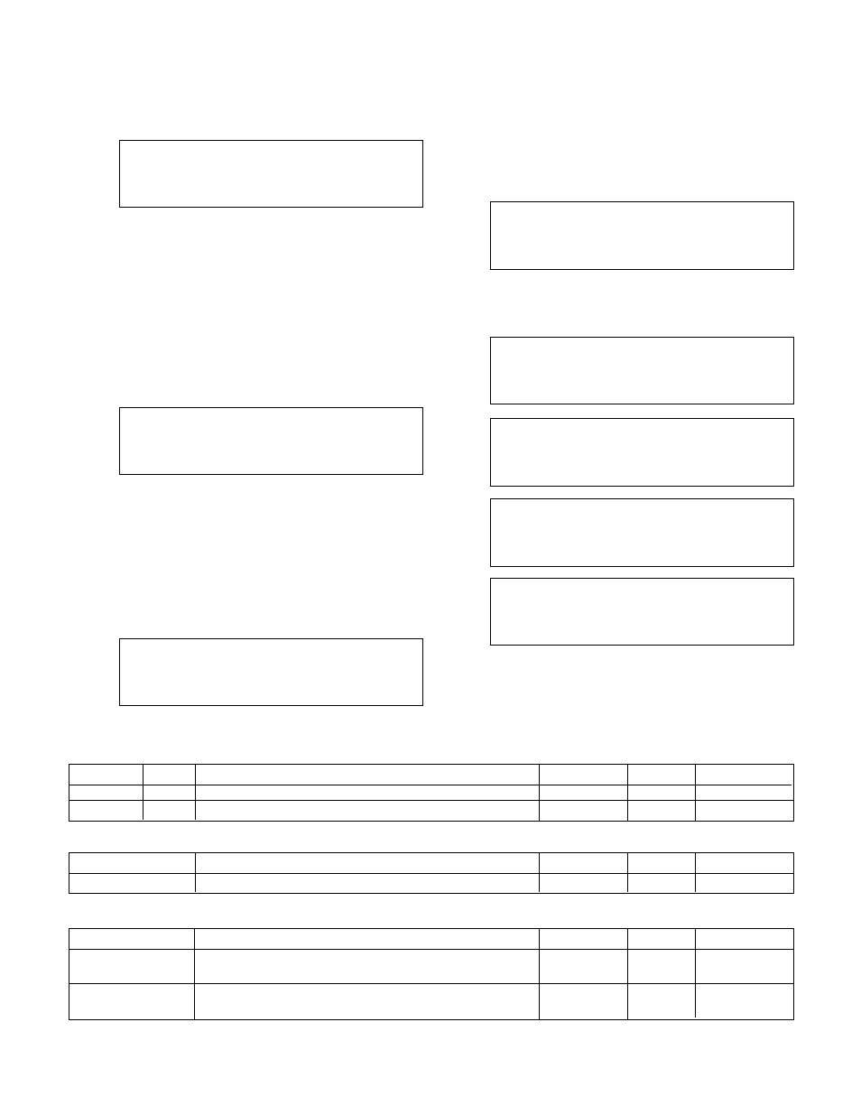
Valve Position Limit
From the Valve Setup screen, shown in section 3.2,
Press 1 and ENTER to get to the Valve Position Limit
screen shown below.
Valve Pos. Limit
Minimum: ###%
Maximum: ###%
0% = Closed OK ? (Y/N)
Press YES and ENTER to accept the values and
return to the Valve Setup screen, shown in section
3.2, or press NO and ENTER to edit the fields. See
Table 6 for a description of the Valve Position Limit
variables.
Note: The minimum and maximum valve position lim-
its are ignored in manual operation mode.
3.2.2
Valve Log Rate
From the Valve Setup screen, shown in section 3.2,
Press 2 and ENTER to get to the Valve Log Rate
screen shown below.
Valve Log Rate: #
0=None
2=Hr
4=Week
1=Min
3=Day
5=Month
OK: ? (Y/N)
Press YES and ENTER to accept the current Valve
Log Rate, or press NO and ENTER to edit the Valve
Log Rate. See section 4.7.4 for more information on
the Valve Log. See Table 7 for a description of the
Valve Log Rate variables.
3.2.3
Valve Signal
From the Valve Setup screen, shown in section 3.2,
Press 3 and ENTER to get to the Valve Signal screen
shown below.
Valve Signal Type: #
1=4-20mA 2=0-10V
Signal Reversed: Y/N
OK: ? (Y/N)
Press YES and ENTER to accept the configuration
and return to the Valve Setup screen shown in sec-
tion 3.2. Press NO and ENTER to edit the fields. See
Table 8 for a description of the Valve Signal variables.
3.3
System Setup
From the Setup Selection screen, shown in section 3,
press the 3 and ENTER to get to the System Setup
screens shown below.
Selection: #
0 = Exit
1 = System Temp Limit
2 = PID
3 = Alarms
Press NEXT SCREEN key or PREV. SCREEN to view
neighboring screens. There are five screens in this
menu. The remaining screens are shown below.
Selection: #
0 = Exit
4 = Flow Limit
5 = System Purge
6 = Reset Totals
Selection: #
0 = Exit
7 = Date, Time
8 = Password
9 = I/O Setup
Selection: #
0 = Exit
10 = Communication
11 = Special Function
12 = Save to Flash
Selection: #
0 = Exit
13 = Load From Flash
14 = Set Contrast
Press the numeric key corresponding to the desired
System Setup sub-menu, and press ENTER.
Variable
Unit
Description
Default Value
Range
Field Value
Minimum
%
Minimum valve position in automatic operation mode
0
0-100
Maximum
%
Maximum valve position in automatic operation mode
100
0-100
Table 6: Valve Position Limit Variables
Variable
Description
Default Value
Range
Field Value
Valve Log Rate
One data point is taken at the end of the interval
0
0-5
Table 7: Valve Log Rate Variables
Variable
Description
Default Value
Range
Field Value
Valve Signal
Select 1 if the valve accepts a 4-20mA signal or select
1
1-2
Type
2 if it accepts a 0-10V signal
Signal Reversed
Select N if the valve is closed at 4mA or 0V. Select Y if
N
Y/N
the valve is open at 4mA or 0V
Table 8: Valve Signal Variables