Bell & Gossett S14333 Technologic 5500 Series ZoneSav Controller User Manual
Page 15
15
If either of the above are set to YES the screen,
shown below, prompts the user to define the pass-
word.
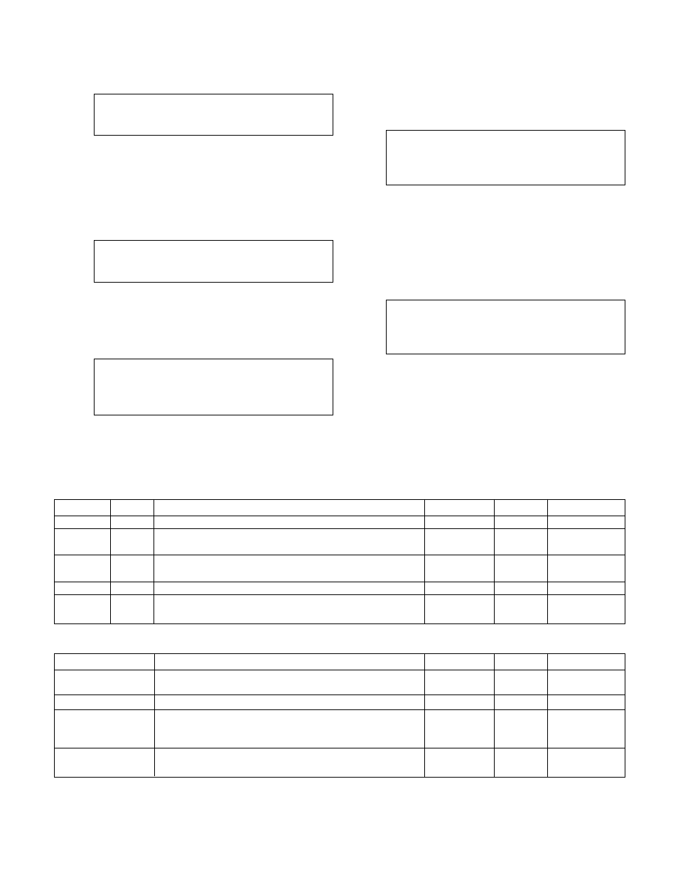
ENTER NEW PASSWORD
>_______________<
Enter a password from 0-999999. Record it here or
somewhere else!
After entering a password the Verify Password screen
requires the user to confirm the password. If the con-
firmed number does not agree with the first number,
the Enter New Password screen is repeated to allow
the user to get both input screens to agree.
VERIFY THE PASSWORD
>_______________<
3.3.9
I/O Setup
From the System Setup Menu, shown in section 3.3,
press 9 and ENTER to get to the I/O Setup screen
shown below.
I/O Setup Select: #
1 = DI
2 = DO
3 = AO
0 = EXIT
Note:
The total available number of I/O to be config-
ured is dependent on the system setup. Complete all
previous setup screens, specifically sensors, prior to
completing the following.
3.3.9.1
DI
From the I/O Setup Menu, shown in section 3.3.9, press
1 and ENTER to get to the DI screen shown below.
Opt. DI = #
Avail: = #
Code = #
Delay = ##s
(Functionality)
Exit: ? (Y/N)
To return to the I/O Setup Menu, shown in section
3.3.9, press YES and ENTER. To edit the fields,
press NO and ENTER. See Table 21 for a description
of the DI variables.
3.3.9.2 DO
From the I/O Setup Menu, shown in section 3.3.9, press
2 and ENTER to get to the DO screen shown below.
Available DOs = ##
Opt. DO# = ####
Code = ###
(Functionality)
Exit: ? (Y/N)
To return to the I/O Setup Menu, shown in section
3.3.9, press YES and ENTER. To edit the fields,
press NO/0 and ENTER. See Table 22 for a descrip-
tion of the DO variables.
Note: DO#1-8 are 24V transistor outputs. DO#9 is a
relay.
Variable
Unit
Description
Default Value
Range
Field Value
Opt. DI
N/A
Enter the DI # that will assume the desired functionality
N/A
0-10
Avail
N/A
This variable is not modifiable. It is here to advise the
N/A
0-9
user of how many digital inputs can be customized
Code
N/A
Defines the desired functionality of the input, valid codes
0
0-3
are defined in Appendix C of this manual
Delay
Seconds
Proof timer
0
0-999
Function-
N/A
This message will show the functionality of the code
N/A
N/A
ality
that was entered
Table 21: DI Variables
Variable
Description
Default Value
Range
Field Value
Available DOs
This screen can not be modified. It is here to advise the
9
0-9
user of how many digital outputs can be customized
Opt. DO#
Enter the DO# that will assume the desired functionality
N/A
0-9
Code
Enter the code to defines the desired functionality of the
0
0-6
output. Valid codes are defined in Appendix C of this
manual
Functionality
This message will show the functionality of the code
N/A
N/A
that was entered
Table 22: DO Variables