Bell & Gossett S14333 Technologic 5500 Series ZoneSav Controller User Manual
Page 21
21
4.1.2
Temperature Status
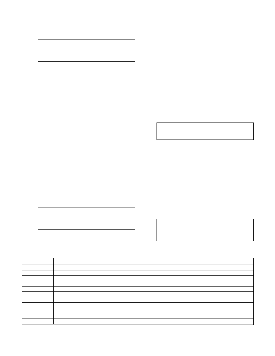
Pressing NEXT SCREEN, the controller will display
the Temperature Status screen shown below.
Temperatures
Sys= ### Zn Sup= ###
*Tmp= ### Zn Ret= ###
Status1 Status2 Status3 Status4
The Temperature Status screen displays all of the
temperatures in the system and the status bar on the
bottom line. It shows the system supply tempera-
ture, the zone supply temperature and the zone
return temperature.
*The fourth temperature, "Tmp", will only be visible if
an analog input is set up with type "Temp".
4.1.3
Flow Status
Pressing NEXT SCREEN, the controller will display
the Flow Status screen shown below.
Sys Flow= ##### GPM
Flow #1= #####
Flow #2= #####
Status1 Status2 Status3 Status4
The Flow Status screen displays all of the flows in the
system and the status bar on the bottom line. This
screen is only available if at least one analog input
has type "Flw". If more than one analog input is set
up to have a type "Flow", then the lowest analog
input number will be the system flow, the next high-
est will be flow #1 and the next highest will be flow
#2. Flow #1 and Flow #2 are only visible if the sen-
sors are set up.
4.1.4
Valve Status
Pressing NEXT SCREEN, the controller will display
the Valve Status screen shown below.
Signal to Vlv = ###%
*Signal from Vlv: ###%
Control: (Control Mode)
Status1 Status2 Status3 Status4
The first line shows the signal to the valve. 0%
should always indicate closed, and 100% should
always indicate open. If this is not correct, see sec-
tion 3.2.3.
The second line shows the signal from valve and will
only be visible if an analog input is set up with type
"VFbk".
The third line shows the control mode. See Table 31
below for a description of the different control modes.
4.2
Valve Operation
The valve position can be controlled manually or
automatically. See the following sections for instruc-
tions on both types of operation.
4.2.1
Manual Valve Operation
To manually control the Valve with the controller, the
operation mode must be set to Manual by pressing
the AUTO/MANUAL key. The system must also be
started by pressing the START/STOP key. The con-
troller must also be in one of the status screens
shown in section 4.1.
The LED on the MANUAL VALVE key will be flashing
if all of the above is true. Press it to go to the Manual
Valve Position Screen shown below.
Valve Position = ###%
0%=Closed 100%=Open
Press Clear to Exit
Input the desired valve position, and press ENTER.
The controller will return to the previous status
screen. The actual output signal to the valve will vary
depending on the valve signal type. See section
3.2.3.
4.2.2
Auto Valve Operation
To automatically control the valve with the controller,
the operation mode must be set to Auto by pressing
the AUTO/MANUAL key. The system must also be
started by pressing the START/STOP key.
4.3
Setpoint Modification
To modify any of the setpoints, press the SETPOINT
key while in one of the status screens shown in sec-
tion 4.1. The following will be displayed.
(Season) Setpoint
Sply SP= ###
Ret. SP= ###
Ok ? (Y/N)
Control Mode
Description
None
No control algorithm is being executed.
Flow Limit
90% of the flow limit value is the setpoint for a user adjustable timer.
Sys Temp
System Temperature is beyond the limit. Valve goes to a predefined position for the duration of a user
adjustable timer
ZR Temp
The zone return temperature is being controlled.
ZS Temp
The zone supply temperature is being controlled.
Purge
The valve goes to a fixed position for a user adjustable timer.
ZR Index
The zone return setpoint is being modified.
ZS Index
The zone supply setpoint is being modified.
PID Opt
PID optimization control is closing the valve.
Auto-Tune
PID Auto-Tuning is in process.
Table 31: Control Modes