Bell & Gossett S14333 Technologic 5500 Series ZoneSav Controller User Manual
Page 11
11
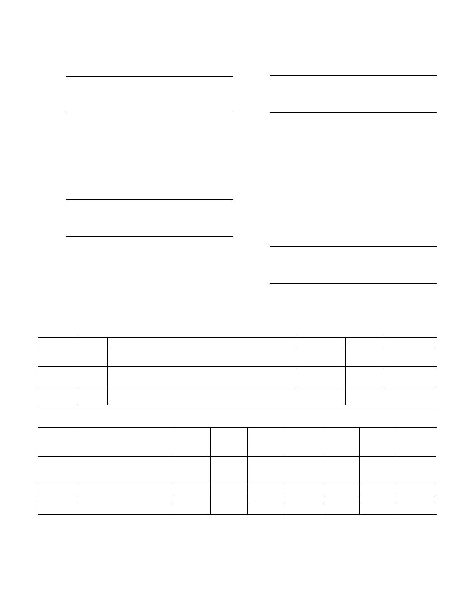
3.3.1
System Temperature Limit
From the System Setup Menu, shown in section 3.3,
press 1 and ENTER to get to the System Tempera-
ture Limit screen shown below.
System Temp Limit
Temp Limit = ###
Valve Opening = ###%
Timer = ###m OK ? (Y/N)
Press NO and ENTER to modify the fields, or press
YES and ENTER to exit back to accept the current
values and return to the System Setup screen, shown
in section 3.3. See Table 9 for a description of the
System Temperature Limit variables.
3.3.2
PID Setup
From the System Setup Menu, shown in section 3.3,
press 2 and ENTER to get to the PID Setup screen
shown below.
PID Selection: #
1 = Values
4 = AutoTune
2 = Index
5 = Optimize
3 = Heat/Cool
0 = Exit
Press the numeric key corresponding to the desired
PID Setup sub-menu, and press ENTER. Press 0 and
ENTER to return to the System Setup screen shown
in section 3.3.
3.3.2.1 PID Values
From the PID Setup screen, shown in section 3.3.2,
press 1 and ENTER to get to the PID Values screen
shown below.
(Type) PID VALUES
P = ###
I = ###
D = ###
Ok ? (Y/N)
There is a different set of values for the zone supply
temperature, zone return temperature and flow.
Press NEXT SCREEN or PREV. SCREEN to change
the type of analog input.
The user should contact B&G if assistance is needed
in tuning the ZoneSav Controller's gains. Also see
section 3.3.2.4 for Auto-Tuning. To edit the fields,
press NO and ENTER. Press YES and ENTER to
accept the values. See Table 10 for a description of
the PID values variables.
3.3.2.2 Setpoint Indexing
From the PID Setup screen, shown in section 3.3.2,
press 2 and ENTER to get to the Setpoint Indexing
screen shown below.
Setpoint Indexing
Sup Idx = #
ZSTmr = ## s
Ret Idx = #
ZRTmr = ## s
Ok ? (Y/N)
Variable
Unit
Description
Default Value
Range
Field Value
Temp
°F
If heating system, this is the low system temperature limit
55
0-999
Limit
If cooling system, this is the high system temperature limit
Valve
%
Valve opens to this position when system temperature
50
0-100
Opening
limit is exceeded
Timer
minutes
Valve will remain at the Valve Opening for the duration
1
0-99
of the timer
Table 9: System Temperature Limit Variables
Variable
Description
Default
Default
Default
Field
Field
Field
Range
Value
Value
Value
Value
Value
Value
(ZS)
(ZR)
(FL)
(ZS)
(ZR)
(FL)
Type
ZS = zone supply
N/A
N/A
N/A
N/A
N/A
N/A
N/A
ZR = zone return
FL = flow
PID-P
Proportional value
400
400
20
1-999
PID-I
Integral value
100
100
20
0-999
PID-D
Derivative value
0
0
0
0-999
Table 10: PID Values