Bell & Gossett S14333 Technologic 5500 Series ZoneSav Controller User Manual
Page 7
7
5) Terminate the negative (-) wire of the sensor to TB
41 of the respective analog input sensor connec-
tion. Terminate the positive (+) wire of the sensor
to the terminal block which is connected to the
positive (+) terminal shown on the Analog input
card.
Note: Be certain that the power supplied to other ter-
minal blocks has not been interrupted! The wires that
were removed in the preceding steps may have been
used as jumpers.
1.11.3
User Configurable I/O
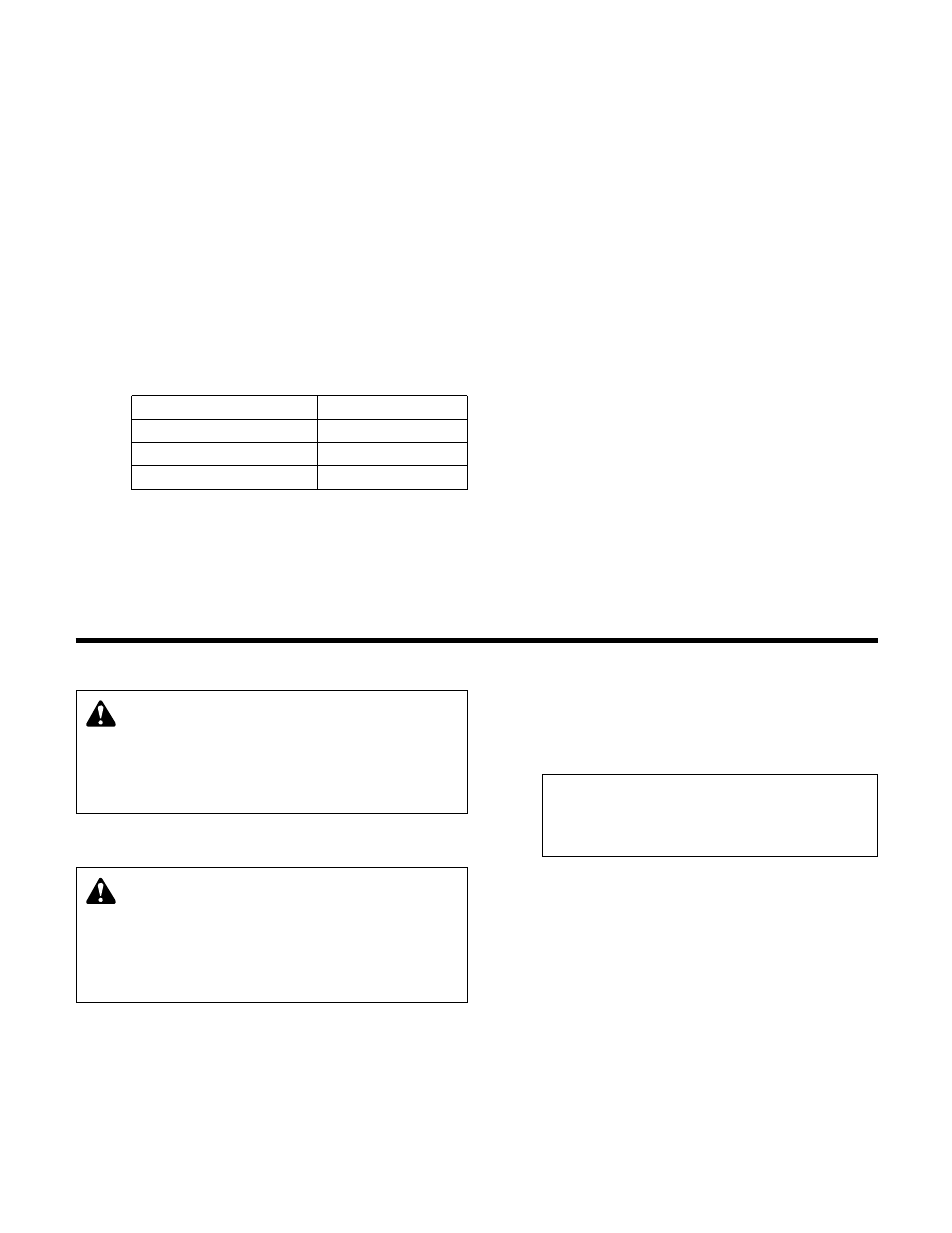
The ZoneSav Controller comes equipped with the
capability to define the operation of any unused input
or output. Table 1 below shows the amount of each
type that is available for user setup on the standard
ZoneSav Controller. This does not include optional
I/O modules or the signals that are required for cor-
rect operation. Refer to Section 3.3.9 for detailed
information on the I/O Setup Menu.
I/O Type
Amount Available
Digital Input (24V)
9
Digital Output (24V)
8 + 1 relay
Analog Output
1
Table 1: User Configuration I/O
1.11.4
Valve
The ZoneSav Controller sends a 4 - 20mA or 0 - 10V
signal to the valve. This signal can also be reversed.
See section 3.2.3, Valve Signal, for instructions on
how to change the signal sent to the valve. The Valve
must be configured to accept a 4 - 20mA or 0 - 10V
signal. All shields must be grounded, only in the
ZoneSav Controller, to prevent ground loops and
improper signals.
1.11.5
Local-Off-Remote Switch
In the LOCAL position, the panel is always energized.
With the LOCAL-OFF-REMOTE switch in REMOTE, a
contact closure from a remote source will energize
the panel. This signal can be supplied through any of
the communications protocols used or through a 24V
digital input.
Section 2 - Operator Interface
2.1
Power-Up
Put LOCAL-REMOTE-OFF (LRO) switch in the
LOCAL position.
Turn main disconnect on.
2.2
ZoneSav Controller Screen
Upon powering up the controller, the display will light
and show the ZoneSav Controller default screen
shown below. See section 4.1 for more description
of this screen and the neighboring status screens.
ZoneSav Controller
Version: #.#
MM/DD/YY HH:MM:SS A/P
Stop Man Heat Manual
2.3
Key Functionality
The names of the keys on the Operator Interface
Panel (OIP) are shown as CAPITAL LETTERS in this
manual. Table 2, on the next page, shows the func-
tionality of the keys on the OIP.
2.4
LEDs
Table 3, shown on the next page, gives the meaning
of the LED states.
WARNING: Electrical shock hazard. Inspect all elec-
trical connections prior to powering the unit. Wiring
connections must be made by a qualified electrician in
accordance with all applicable codes, ordinances, and
good practices. FAILURE TO FOLLOW THESE INSTRUC-
TIONS COULD RESULT IN SERIOUS PERSONAL
INJURY, DEATH, AND/OR PROPERTY DAMAGE.
WARNING: Electrical shock hazard. Multiple power
sources. The off position of the LOCAL-REMOTE-
OFF switch does not disconnect all of the power sources in
the technologic panel. All power sources must be discon-
nected prior to entering the control panel. FAILURE TO
FOLLOW THESE INSTRUCTIONS COULD RESULT IN
SERIOUS PERSONAL INJURY, DEATH, AND/OR PROP-
ERTY DAMAGE.