Bell & Gossett S14333 Technologic 5500 Series ZoneSav Controller User Manual
Page 8
8
From the ZoneSav Controller screen, shown in sec-
tion 2.2, press the SETUP key to get to the Setup
Selection screen shown below.
Setup Selection: 0
1 = Sensors
4 = Test
2 = Valve
5 = Default
3 = System
0 = Exit
Press the numeric key corresponding to the desired
Setup Selection submenu, and press ENTER.
3.1
Sensor Setup
From the Setup Selection Menu, shown in section 3,
press 1 and ENTER to get to the Sensor Setup
screen shown below.
Sensor Setup: #
1=Sensor Settings
2=Sensor Log Rate
0=Exit
Press the numeric key corresponding to the desired
Sensor Setup submenu and press ENTER.
3.1.1
Sensor Settings
3.1.1.1 Sensor Number
From the Sensor Setup screen, shown in section 3.1,
Press 1 and ENTER to get to the Sensor Number
screen shown below.
SENSOR NO: ##
Input the analog input number that will be modified,
and press ENTER.
3.1.1.2 Sensor Edit
After the analog input number is entered section
3.1.1.1, the Sensor Edit screen, shown below, will be
displayed.
Sensor# ##
Type: (Type)
Span = 0
Zero = 0
Override:Y/N
Ok ? (Y/N)
Press YES and ENTER at the Ok prompt to accept
these values, and proceed to section 3.1.1.7. Press
NO and ENTER to modify these values, and go to
section 3.1.1.3.
Section 3 - Setup Selection
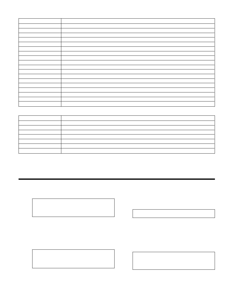
Key Name
Functionality
START/STOP
Starts and Stops System
AUTO/MANUAL
Toggles operation mode
MANUAL VALVE
Brings up the manual valve position screen. See section 4.2.1.
WARNING
Brings up the active warnings if a warning exists (LED will blink when active)
PREV. SCREEN
Navigates to neighboring screens (LED will blink when active)
NEXT SCREEN
Navigates to neighboring screens (LED will blink when active)
HELP
Brings up alarms. See section 4.5. If no alarm exists, help is available in every screen.
PROCESS VARIABLE/1
Brings up the Process Variable screen, shown in section 4.4, or used as a numeric key
SET POINT/2
Brings up the Set Point screen, shown in section 4.3, or used as a numeric key
SETUP/3
Brings up the Setup screen, shown in section 3, or used as a numeric key
F1/LOG/5
Brings up the Log Menu, shown in section 4.7, or used as a numeric key
F2/6
Used as a numeric key or an up arrow
YES/7
Used as a numeric key or YES
F3/INFO/8
Shows controller information screen, shown in section 5.13, or used as a numeric key
F4/9
Used as a numeric key or a down arrow
NO/0
Used as a numeric key or NO
ENTER
Used to confirm entries and to advance to the next item if there are multiple fields
CLEAR
Used to clear entries and to exit some screens
Table 2: Key Functionality
LED
Description
START/STOP
On = Start, Blinking = Stop
AUTO/MANUAL
On = Auto, Blinking = Manual
MANUAL VALVE
Blinks when system is on and in manual and in status screens to indicate it is active
WARNING
Blinks when a warning exists and in status screens to indicate it is active
PREV. SCREEN
Blinks when button is active
NEXT SCREEN
Blinks when button is active
HELP
Off = Brings up Help screen when pressed, Blinking = Brings up alarms when pressed.
Table 3