Bell & Gossett S14333 Technologic 5500 Series ZoneSav Controller User Manual
Page 20
20
If the controller is communicating properly with the
building automation system, the numbers will contin-
ue increasing in value. For Modbus protocol, the read
and write numbers will be equal. For BACnet and
Johnson N2 protocols, the numbers will not be equal.
If the numbers are not increasing in value, the con-
troller is not communicating properly. If it is not com-
municating, check the wiring at the terminal blocks
and the RS communication card mounted on the
controller. Consult the Tech 5500 Serial Communi-
cation Manual for further assistance. Press CLEAR
to exit this test.
3.5
Default Setup
From the Setup Selection Menu, shown in section 3,
press 5 and ENTER to get to the Default screen
shown below.
*** WARNING ***
All Setup Data Will
Be Overwritten.
Proceed: ? (Y/N)
Prior to reverting to the default values, it is strongly
recommended that all factory/field variables be
recorded for future reference. Use the 'Field Value'
location in the tables to record your current data.
Also record your sensor and valve setup information
on the wiring diagram that was included with the unit.
Press NO to return to the Setup Selection Menu,
shown in section 3, without loading the default val-
ues. Press YES to load all of the pre-defined default
variables defined in the tables in this manual. Once
the default values are loaded, the controller will return
to the Setup Selection screen shown in section 3.
4.1
Status Screens
There are at least 3 status screens that can be navi-
gated by pressing NEXT SCREEN or PREV. SCREEN.
Many screens can only be accessed from the status
screens including: the Alarm screen, Warning screen,
Process Variable screen, Setpoint screen, Setup
Selection screen, Log screen, Info screen, and the
Manual Valve screen.
4.1.1
ZoneSav Controller Screen
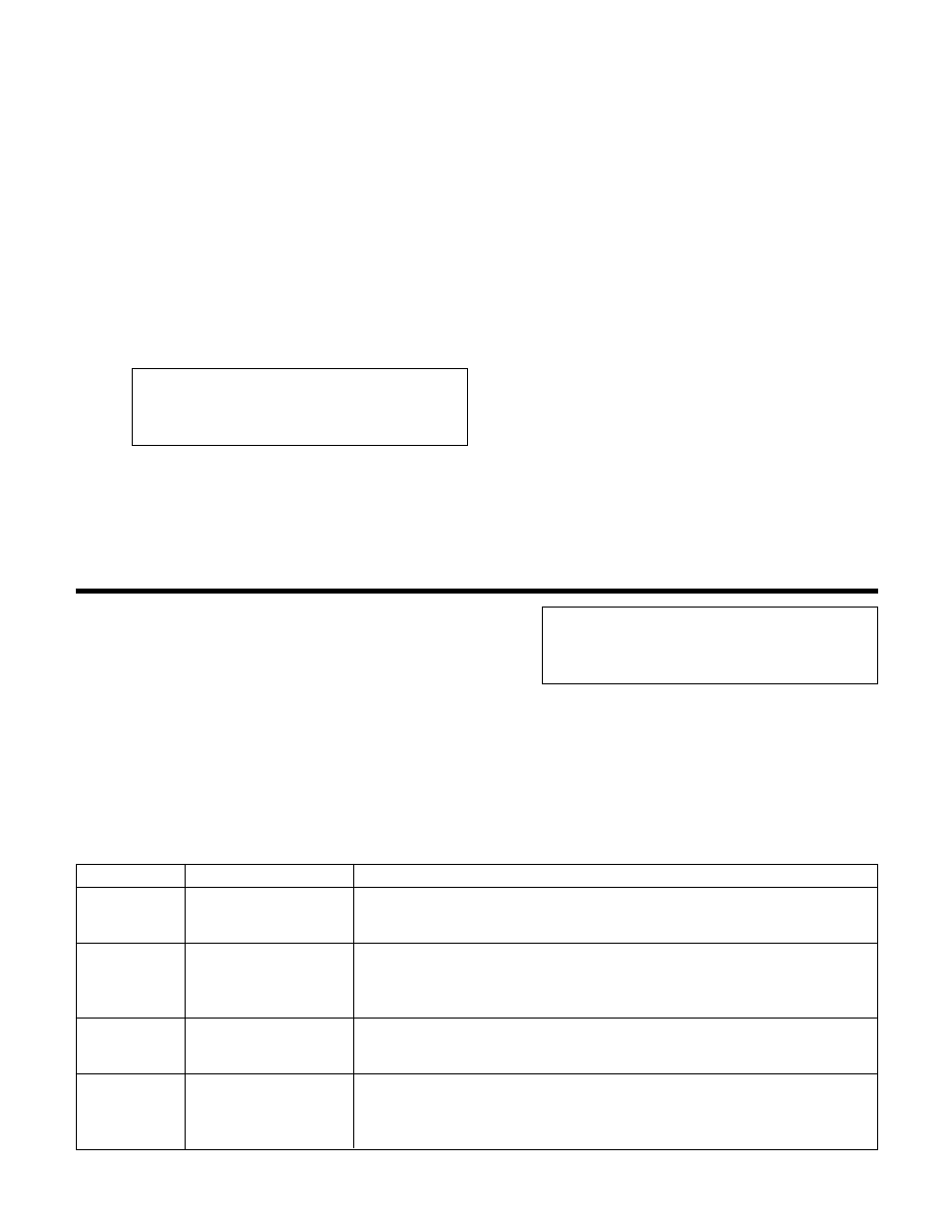
The ZoneSav Controller screen, shown below, is one
of at least 3 status screens. It displays the date,
time, and the version number. It also displays a sta-
tus bar on the bottom line. See Table 30 below for a
description of the status messages.
ZoneSav Controller
Version: #:##
MM/DD/YY HH:MM:SS
Status1 Status2 Status3 Status4
During normal operation, PREV. SCREEN and NEXT
SCREEN can be pressed to scroll through the status
screens shown below.
Section 4 - Operation
Possible States
Description
Status 1
STOP/START
STOP: The valve will close.
START: The valve can be controlled in auto or manual mode.
Press the START/STOP button to toggle.
Status 2
MAN/AUTO
MAN: The user can manually set the valve position by first pressing the
MANUAL VALVE key.
AUTO: The control algorithms will determine the position of the valve.
Press the AUTO/MANUAL key to toggle.
Status 3
HEAT/COOL
HEAT: The system is intended for heating.
COOL: The system is intended for cooling.
See section 3.3.2.3.
Status 4
ALRM/WARN/NORM
NORM: no alarms or warnings
WARN: warning but no alarm
ALRM: alarm
See section 4.5
Table 30: Status Bar