Bell & Gossett S14333 Technologic 5500 Series ZoneSav Controller User Manual
Page 13
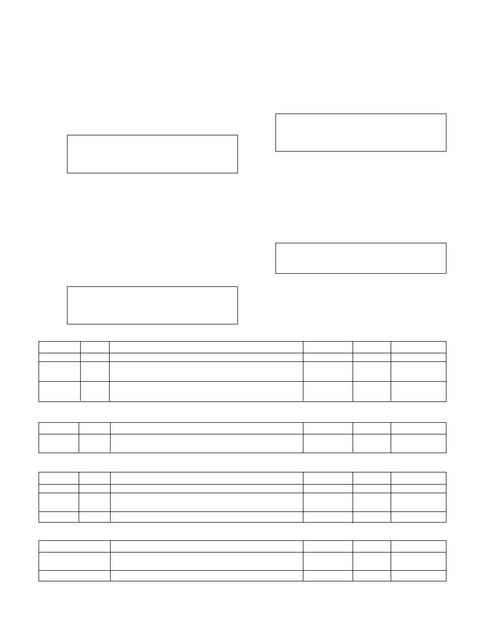
Table 14: Optimize Variables
13
If a "Tune" message does not change to "Comp" or
"Err" within 10 minutes, enter 0 to manually stop the
Auto-Tuning process. If the "Err" message is dis-
played in any of the fields, repeat the Auto-Tune
process. If the error persists, check the Auto-Tune
Log shown in section 4.7.9, record the information,
and contact B&G for assistance.
3.3.2.5 Optimize
From the PID Setup Menu, shown in section 3.3.2,
press 5 and ENTER to get to the Optimize screen
shown below.
PID Opti.: ? (Y/N)
Floating Range: ###%
Holding Time: ###s
Ok ? (Y/N)
Press YES and ENTER to accept the values and
return to the PID Setup Menu shown in section 3.3.2,
or press NO and ENTER to edit the fields. See Table
14 for a description of the Optimize Variables.
PID optimization is used to close the valve as much
as possible while still meeting the zone supply and
zone return setpoints.
3.3.3
Alarms Setup
From the System Setup Menu, shown in section 3.3,
press 3 and ENTER to get to the Alarms Setup
screen shown below.
AI Fail Pr. Tm = ##s
Ok ? (Y/N)
Press YES and ENTER to accept the value and return
to the System Setup Menu, shown in section 3.3, or
press NO and ENTER to edit the field. See Table 15
for a description of the Alarms Variables.
3.3.4
Flow Limit
From the System Setup screen, shown in section 3.3,
press 4 and ENTER to get to the Flow Limit screen
shown below.
Flow Limit
Pr. Tmr = ### sec
LimTm = #
AvgTmr = #
Ok ? YN
To return to the System Setup Menu, shown in sec-
tion 3.3, press YES and ENTER. To edit the fields,
press NO and ENTER. See Table 16 for a descrip-
tion of the Flow Limit variables. See Table 31 for
more information on flow limit operation.
3.3.5
System Purge
From the System Setup Menu, shown in section 3.3,
press 5 and ENTER to get to the System Purge
screen shown below.
Purge Timer = ###m
Valve Position = ###%
Ok ? (Y/N)
To return to the System Setup screen, shown in sec-
tion 3.3, press YES and ENTER.
To edit the fields, press NO and ENTER. See Table
17 for a description of the Bypass Setup variables.
Variable
Unit
Description
Default Value
Range
Field Value
PID Opti
N/A
Select Y to enable PID optimization or N to disable
N
Y/N
Floating
%
The percentage by which the valve position will be
3
0-20
Range
decreased
Holding
s
Proof timer prior to decreasing valve position by the
20
0-999
Time
floating range
Variable
Unit
Description
Default Value
Range
Field Value
AI Fail
Seconds
Proof timer prior to setting an analog input failure alarm
10
0-999
Pr. Tm
Table 15: Alarm Variables
Variable
Unit
Description
Default Value
Range
Field Value
Pr. Tmr
Seconds
Proof timer prior to starting flow limit operation
30
0-999
Lim Tmr
Minutes
The controller will remain in flow limit operation for the
0
0-999
duration of the timer, 0 will disable flow limit
Limit
GPM
Maximum flow before entering flow limit operation
40
0-65535
Table 16: Flow Limit Variables
Variable
Description
Default Value
Range
Field Value
Purge Timer
The valve will remain at the Valve Position for the duration
0
0-30
of the Purge Timer. 0 min will disable purging.
Valve Position
Valve will go to this position during purging.
100
0-100
Table 17: System Purge Variables