GE Industrial Solutions GERAPID 2508, 4008, 5008, 6008 WITH ARC CHUTE 1X2 User Manual
Page 48
48
Design and specifications are subject to change without notice
S47183De rev.02 2011-03-14
6.2.1 Contact system
.
Pay attention to the warnings, Section 1!
This section refers to maintenance works A, B, C from
Fig. 6.1
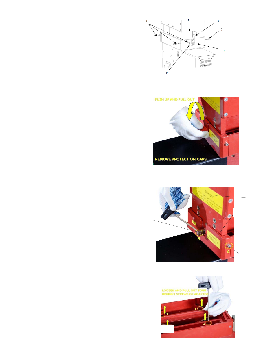
A) Remove the protection caps
[Fig 48] Remove front and rear arc runner protection caps
(1) by sliding up and out.
[Fig. 41]. Using SW5 hex wrench, remove front and rear arc
runner screws (2). Remove the six arc chute attachment
screws (3) from front, rear and sides of the adapter (4).
Lift arc chute (5) up and out of the adapter.
B) Remove the arc chute adapter
[Fig. 49-1]. To dismantle the arc chute adapter, loosen and
pull out the four screws (1) using SW5 tool. Pay attention
that no screws or washers fall inside the breaker!
[Fig. 49-2]. Draw apart and lift off both halves of the
adapter (2). Then pull out two protective walls (3).
C) Changing the protective walls, arc runners and arcing
contacts
[Fig. 49-2]. Pull out two protective walls (3).
[Fig. 50-1 thru 50-4]. Loosen screw (5a) with tool (SW5) and
take out the front arc runner (5).
[Fig. 50-5]. Take out the back arc runner (4) by loosening
two screws (4a) with tool (SW5). Do not remove the
protective cap (4b) from the arc runner (4).
[Fig. 50-6]. Loosen and take out screw (7) including locking
plate (8). Do not split up screw and locking plate!
[Fig. 50-7, 50-8]. Pull out axis pin (9). Pull out arcing contact
(10) and replace with new arcing contact.
[Fig. 50-6, 50-7]. Replace axis pin (9) and secure it with the
locking plate (8). Tighten screw (7) with torque of 10 Nm
[88 in-lbs].
[Fig. 50-1 thru 50-5]. Install front-arc runner (5) and back-
arc runner (4). Tighten screws using torque of 10 Nm
[88 in-lbs].
[Fig. 49-2]. Put in two protective walls (3).
D) Install the adapter
[Fig. 49-2]. Install two protective walls (3). Use new ones if
necessary. Install two parings of adapter (2) and tighten
screws (1); use 5 Nm [44 in-lbs].
E) Install the arc chute
[Fig. 41]. Put arc chute (5) into adapter (4).
[Fig. 41]. Tighten front and backside connections of the arc
runners (2), including lock washer. Use a torque of 10 Nm [88
in-lbs].
[Fig. 41]. Tighten front, rear and side of the arc chute
connections (3), including flat washers. Use a torque of 5 Nm
[44 in-lbs].
[Fig. 41]. Put on isolation caps (1).
Fig 48 Removing the arc chute
Fig. 48-1 Protection Cap removal
Fig 48-2 Arc Runner Screws
Fig. 49-1 Removing Adapter screws
3
1
2
4