GE Industrial Solutions GERAPID 2508, 4008, 5008, 6008 WITH ARC CHUTE 1X2 User Manual
Page 23
2011-03-14 S47183De rev.01
Design and specifications are subject to change without notice
23
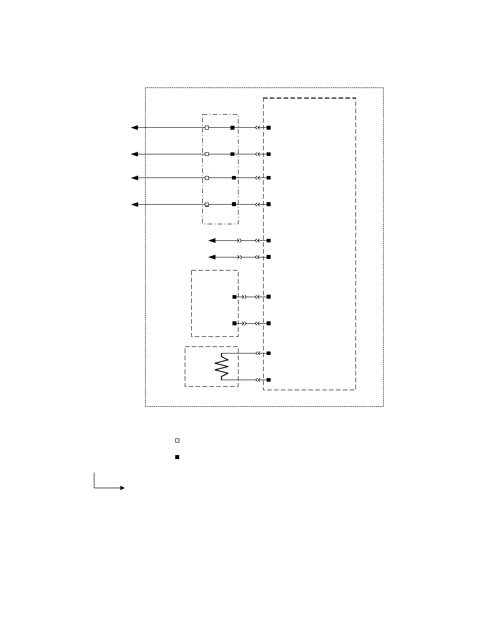
4.3.6 Zero voltage release control circuit
The closing STOP signal is provided for resetting K2 on the SU-control circuit. It effects with priority in switching
OFF (by ST or UVR) before switching ON. Once switching ON and OFF signals are simultaneous, switching OFF
command will stay longer than switching ON. This means the OFF command is master command.
-S2 (-X2 :6/:7) is NO contact, utilized for indirect releasing of the UVR by relay -K2
-S2 (-X2 :8/:9) is NC contact utilized for direct releasing of the UVR. If it’s not used, please short this connection
permanently.
Fig. 28 UVR control circuit
Key position - 5
Key number - 00: Without shunt trip or zero voltage release.
Key number - 20: With zero voltage release.
36/ _ _ _ X _ _ _
1
2
3
4
5
6
8 (+)
7 (-)
9
10
-X10/X11: PCB
-X14 : UVR PCB
9 (+)
7 (-)
24VDC
External Trip
Signal, N.C.
Contact
Internal Close Stop
Interlocking To
Other PCBs
UVR Coil
Undervoltage Relea
s
e
D
e
v
ice
Pr
in
te
d
C
ir
c
u
it
B
o
ar
d
Breaker
PCB - Printed Circuit Board
Zero Voltage Release Circuit
- User external connection point
- Factory internal connection point
-X2:
9
8
External Trip
Signal, N.O.
Contact
7
6