GE Industrial Solutions GERAPID 2508, 4008, 5008, 6008 WITH ARC CHUTE 1X2 User Manual
Page 47
2011-03-14 S47183De rev.01
Design and specifications are subject to change without notice
47
6.2 List of maintenance tasks
TYPE OF THE WORK
BY WHOM
WHEN REQUIRED
RECOMMENDATIONS
A.
Arc chute changing
-Customer
-Trained technician
As a result of the inspection C
B.
Arcing contact and arc
runners changing
-Customer
-Trained technician
As a result of the inspection C
Replace complete arcing set.
C.
Protective walls changing
-Customer
-Trained technician
As a result of the inspection C
D.
Adjustment of the
contacts
-GE Service Engr
As a result of the inspection C
Only when replacement of the arcing
contact results with incorrect gaps.
See point 6.1.5.
E.
Replacement of the
control board
-Customer
-Trained technician
As a result of the inspection B,E
F.
Adjustment of the
mechanism
-GE Service Engr
As a result of the inspection B,E
G.
Flexband or fixed contact
changing
-GE Service Engr
As a result of the inspection C,E
H.
Mechanism changing
-GE Service Engr
As a result of the inspection B,E
I.
Trip unit changing &
adjustment
-GE Service Engr
As a result of the inspection B,E
J.
Auxiliary contacts
adjustment and changing
-Customer
-Trained technician
As a result of the inspection B,E
In case of improper operation of the
switches, adjustment might be
necessary.
K.
Drive changing
-GE Service Engr
As a result of the inspection B,E
L.
Accessories changing
-GE Service Engr
As a result of the inspection B,E
Table 4
Required tools:
Cleaning tissue
Pocket lamp
Hand lever
Hexagon wrench SW 4, SW 5, SW 6
Screw wrench SW 10, SW 13
Torx® wrench size 30, 40 and 45
Small and medium screwdriver
Pliers
Wire cutter
File
Steel brush
Safety hints:
Securing against falling parts
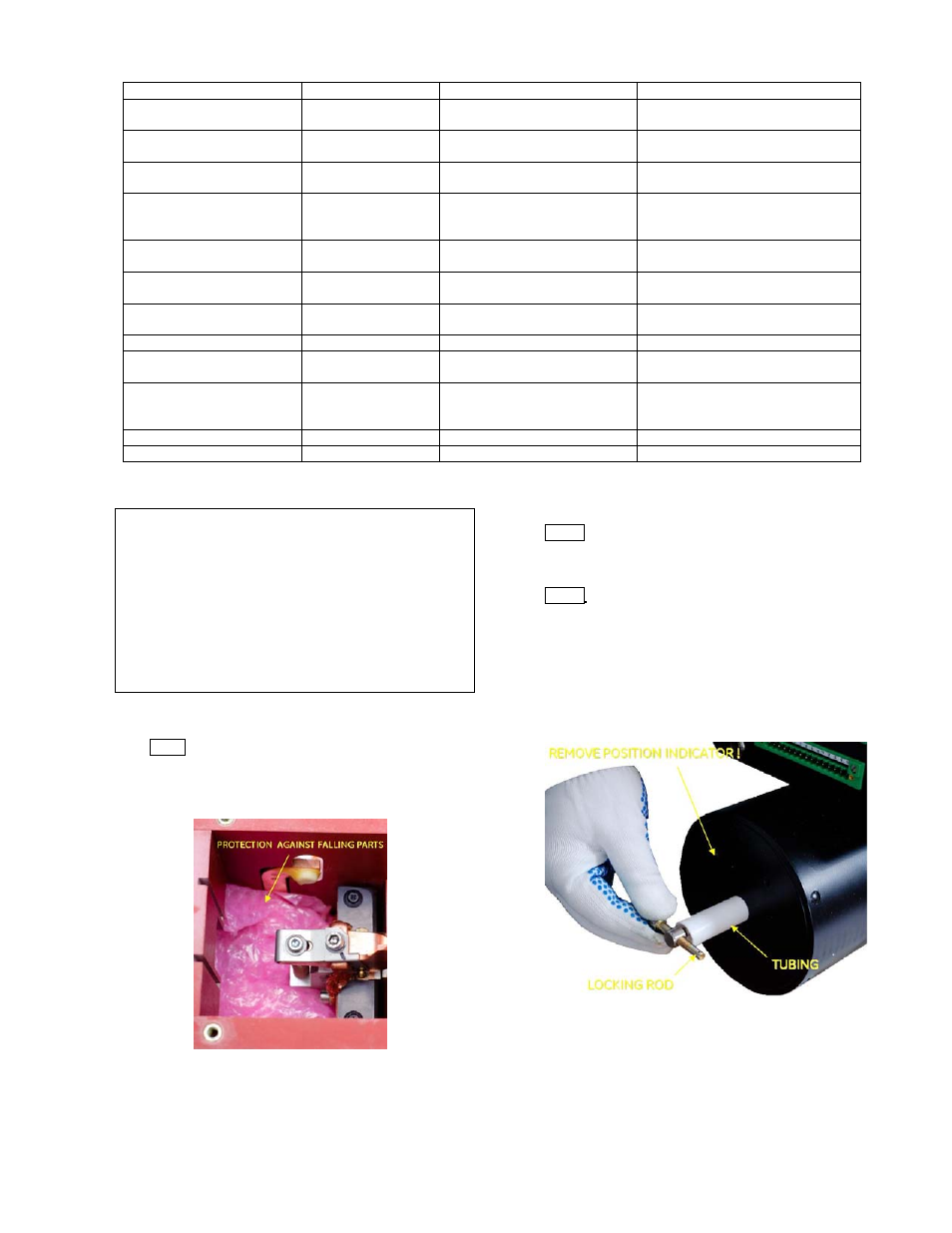
Hint 1
Place a cloth into the lower area of the arcing
contact [Fig. a]. Remember to secure the closing drive
according to Hint 3.
Fig. a Protecting of the arcing area against falling parts
Maintenance with zero voltage release
Hint 2
If an optional zero voltage release is installed, it
must be energized to enable closing of the breaker. Only
then maintenance of the arcing contacts is possible.
Hint 3
To prevent the risk of injury, it is recommended
to secure the breaker in the closed position with a simple
mechanical interlock device [Fig. b]. A piece of tubing
having ~50 mm [~2 in] length and inner diameter of
minimum 14 mm [0,55 in] works well. The outer diameter
of the locking rod shall be less 8 mm [0,3 in]. GE does not
offer this locking device.
Fig. b Securing closing drive against opening