GE Industrial Solutions GERAPID 2508, 4008, 5008, 6008 WITH ARC CHUTE 1X2 User Manual
Page 45
2011-03-14 S47183De rev.01
Design and specifications are subject to change without notice
45
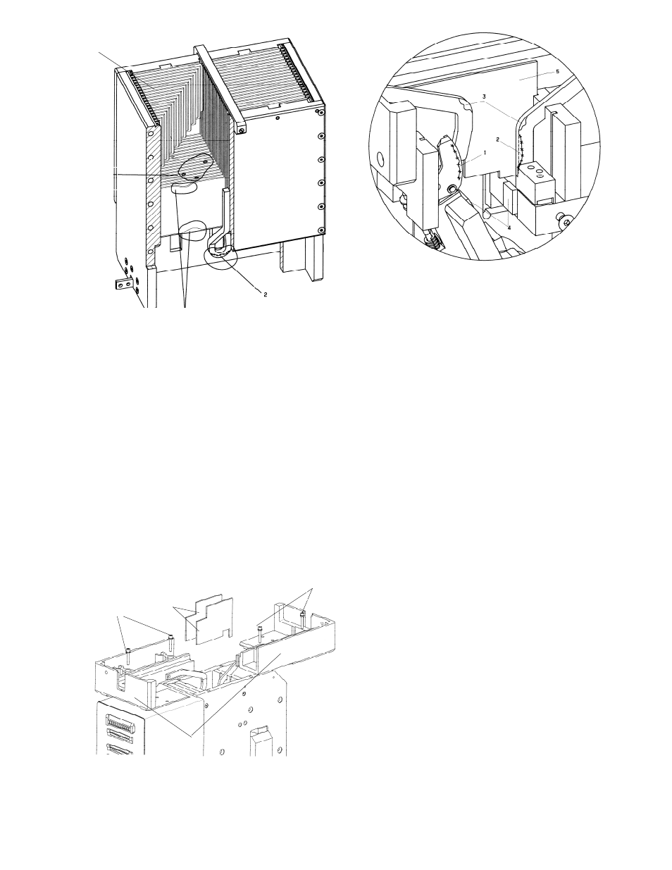
Fig. 42 Inspection of the arc chute
6.1.4 Inspection of the contact system
Pay attention to the warnings, Section 1!
A) Remove the arc chute
[Fig. 41]. Remove front and rear arc runner protection caps
(1) by sliding up and out.
[Fig. 41]. Using SW5 hex wrench, remove front and rear arc
runner screws (2). Remove the six arc chute attachment
screws (3) from front, rear and sides of the adapter (4). Lift
arc chute (5) up and out of the adapter
B) Remove the arc chute adapter
[Fig. 43]. To dismantle the arc chute adapter, loosen and
pull out the four upright screws (1) using SW5 tool. Pay
attention that no screws or washers fall inside the breaker!
[Fig. 43]. Draw aside and lift off both parings of adapter (2).
Then pull out two protective walls (3).
Fig. 43 Adapter and protective walls
Fig. 44 Checking the contact system
C) Check the protective walls
[Fig. 44]. The material burn out on the protective walls (5)
shall not exceed 1 mm [0.04 in] at any place.
D) Check the arc runners
[Fig. 44]. The arc runners should not be burned more than
30 % of its total cross section. Pay particular attention to the
area around arc runner bend (3) and at contact point with
arcing contact (2).
E) Check the arcing contact
[Fig. 44]. Wear of the arcing contact (1) must not exceed
2 mm [0.08 in] of its depth. Replace the arcing contact in that
case. If contact erosion exceeds 4 mm [0.16 in], major
contact system failure is possible.
F) Check the main contacts
[Fig. 44]. The main contacts (4) shall not show any
particular signs of material erosion, since the arc is ignited
between the arcing contacts. It means, that for rated and
overload currents there should be no erosion of main
contacts.
Erosion of main contacts can take place only in case of
excessively worn, highly burned arcing contact or during
very high short circuit currents. In that case wear must not
exceed 1.5 mm [0.06 in].
G) Install the adapter
[Fig. 43]. Install the two protective walls (3). Use new ones if
necessary. Install two parings of adapter (2) and tighten
screws (1) use 10 Nm [88 in-lbs].
H) Install the arc chute
[Fig. 41]. Put arc chute (5) into adapter (4).
[Fig. 41]. Tighten front and backside connections of the arc
runners (2), including lock washer. Use a torque of 10 Nm [88
in-lbs].
[Fig. 41]. Tighten front, rear and side of the arc chute
connections (3), including flat washers. Use a torque of 5 Nm
[44 in-lbs].
[Fig. 41]. Put on isolation caps (1).
`
1
3
2
4
2
1
3
1
6.1.1 General visual inspection