GE Industrial Solutions GERAPID 2508, 4008, 5008, 6008 WITH ARC CHUTE 1X2 User Manual
Page 4
4
Design and specifications are subject to change without notice
S47183De rev.02 2011-03-14
2.2 Installation
2.2.1 Operational environment
The breaker, as delivered, is NEMA 1 protected. It is intended
for service in indoor applications, without pollution, with non-
conductive dust, protected against high humidity and heavy
condensation. Low conductivity dust deposit due to frequent
condensation of humidity is acceptable. For general
environmental conditions refer to EN 50123-1 - annex B, and
IEC 60947, class PD3.
The breaker can operate at rated current within ambient
temperature range of –5 °C to +40 °C (23 °F to 104 °F).
Maximum operating ambient temperature is +55 °C (131 °F)
with continuous current derated by 10 %.
The breaker can operate at altitudes up to 2000 m (~6500 ft)
without derating.
The breaker shall not be subjected to strong vibrations.
Maximum vibrations of 0.5 g per 30 sec in vertical and
horizontal directions are allowed.
Air shall be clean and its relative humidity shall be not more
than 50 % r.h. at the maximum temperature of +40 °C
(104 °F). Relative humidity may be higher if the temperatures
are lower, for example, 90 %r.h. at +20 °C (68 °F). Slight
condensation might occur during variations of temperature.
2.2.2 Installation and interfaces
The lower and upper main terminals must be connected
directly to the main cables or bus bars.
WARNING: The breaker must only be used in an upright
operation position with the arc chute in place and fully
secured.
After arc chute installation check for tightness both
connections to the arc runners. See Fig. 48-2
The safety distances as listed in section 5.1 shall be
maintained to grounded or insulated parts. Suitable measures
must be taken to protect personnel from arcs.
Strong, external magnetic fields, caused by improperly
located supply conductors or stray fields from other devices,
can lead to a shift of the trip setting thresholds. This may
result in premature tripping, or no tripping at all during low-
level short circuit current events. This has to be accounted for
when installing and operating the device with shielding added
if appropriate.
The control wires must be connected to the control terminals
as shown in the schematic circuit diagrams. The protective
grounding wire must be connected at the marked contact
[Fig. 2].
Fig. 2 Termination for grounding wire
2.3 Usage
2.3.1 Supply and load
In accordance with its type, the breaker has been designed
for the current and voltage listed in Table 1, section 3.3.
During continuous operation, breaker must only be loaded up
to its maximum rated current. Load currents in excess of
breaker nameplate rating are allowable for brief periods only.
Refer to the short time currents listed in Table 1.
Do not exceed the rated nominal voltage shown on the
breaker’s nameplate.
Supply voltage for the drive and the auxiliary-tripping devices
shall be within the specified control voltage range. Maximum
current values for the auxiliary-tripping devices are listed in
Table 2a.
WARNING: Plugging in or unplugging of the auxiliary
connectors (-X2 :1/:2) (-X3 :4/:5) is only allowed with
disconnected primary (mains) and secondary voltages.
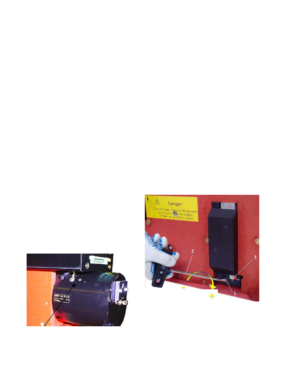
2.3.2 Adjusting the over current release
OCT is an over-current tripping release , which trips and
releases the breaker in case of overload or short circuit
currents. This is an instantaneous and direct acting device.
If equipped with an adjustable OCT, the response threshold
can be easily adjusted [Fig.3], by turning the adjustment nut
(1) with a SW6 hexagon wrench (2).
The adjustment must only be carried out after the breaker
has been disconnected from the main circuit. For fixed
installations breaker’s main terminals shall be grounded.
Turning the adjustment screw clockwise increases the trip
threshold, turning the screw counter-clockwise decreases the
tripping threshold. Align the arrow and the desired marking 3,
to perform adjustment.
Fig. 3 Setting of the OCT unit