J3 j2 x1, Jp3 x2, 4 customer interface board (option) – GE Industrial Solutions LP 33 Series 30 & 40 kVA Installation Guide User Manual
Page 38
Modifications reserved
Page 38/41
OPM_LPS_3UI_30K_40K_0US_V010.doc
Installation Guide LP 33 Series 10-20 kVA
4.4 CUSTOMER INTERFACE BOARD (OPTION)
WARNING !
The installation and cabling of the options must be performed by
QUALIFIED SERVICE PERSON.
Serial port J3 - RS232 (sub - D - female 9 pin)
Total remote management of the system using new
generation software JUMP (Java Universal Management
Platform) for system protection and management of
systems using GE UPS’s.
JUMP system is written in JAVA and supports virtually all
platforms having JAVA runtime environment.
Pin 2: TX (out)
Pin 3: RX (in)
Pin 5: GND
J2 (sub – D female 25p) – Output signals on voltage-free contacts
J2 / 1, 2, 3
NO, C, NC
Utility failure
(default Parameter RL=1)
J2 / 4, 5, 6
NO, C, NC
Load on inverter
(default Parameter RL=3)
J2 / 7, 8, 9
NO, C, NC
Stop operation
(default Parameter RL=5)
J2 / 14, 15, 16
NO, C, NC
Load on utility
(default Parameter RL=2)
J2 / 17, 18, 19
NO, C, NC
General alarm (NO)
(default Parameter RL=4)
J2 / 20, 21, 22
NO, C, NC
Buzzer
(default Parameter RL=6)
Signals on terminals X1 and on connector J2 are in parallel and
therefore not separated galvanically from each other.
The programmable signals on X1 and J2 will be disabled with Q1
open, with the exception of the signals for:
16 – Manual bypass ON
24 – Relay output ON
25 – Relay output OFF
26 – EPO
X1 – Output signals on voltage-free contacts
X1 / 1, 2, 3
NO, C, NC
Utility failure
(default Parameter RL=1)
X1 / 4, 5, 6
NO, C, NC
Load on inverter
(default Parameter RL=3)
X1 / 7, 8, 9
NO, C, NC
Stop operation
(default Parameter RL=5)
X1 / 12, 13, 14
NO, C, NC
Load on utility
(default Parameter RL=2)
X1 / 15, 16, 17
NO, C, NC
General alarm (NO)
(default Parameter RL=4)
X1 / 18, 19, 20
NO, C, NC
Buzzer (default
Parameter
RL=6)
X2 – Terminals EPO connection (Emergency Power Off)
X2 / 1, 2 or J2 / 12, 25
NC
EPO (Emergency Power Off)
LPS33U
_Cust
omer i
nterfac
e_01
12
3
4
5
6
789
10
11
16
15
14
13
12
22
21
20
19
18
17
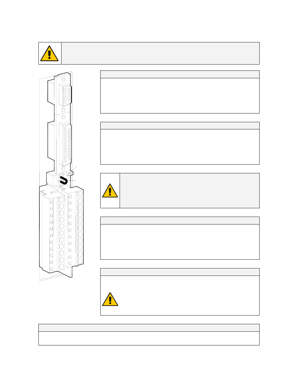
J3
J2
X1
2
1
JP3
X2
Fig. 4.4-1 Customer Interface
C
=
Common
NO
=
Normally Open
NC
=
Normally Closed
To enable this function, remove jumper JP3 on the Customer
Interface and the cable on the terminal X2 / 1, 2.
(See Fig. 4.4-1).
Verify if the cable on the terminal X7 / 1, 2 and jumper JP5 on the
P1 – Control board are OFF (see Fig. 4.4-3).
Programmable functions on input contacts
X1/10, 21 or J2/10, 23
Programmable
(default Parameter = RL1)
X1/11, 22 or J2/11, 24
Programmable / Generator ON (NO)
(default Parameter = RL2)