Digital energy tm l p se ries, Fig. 3.4-3 fixing of the ups cabinet on the floor, Fig. 3.4-4 ups cabinet floor fixing points – GE Industrial Solutions LP 33 Series 30 & 40 kVA Installation Guide User Manual
Page 16
Modifications reserved
Page 16/41
OPM_LPS_3UI_30K_40K_0US_V010.doc
Installation Guide LP 33 Series 10-20 kVA
Opening for input and output cable connections LP 33 Series
LP
S33U_03
0
-0
40_UPS vi
ew bot
to
m
_01
19
5m
m
512mm
44mm
44mm
12
6mm
20.16"
1.74"
1.74"
7.
68
"
4
.9
6"
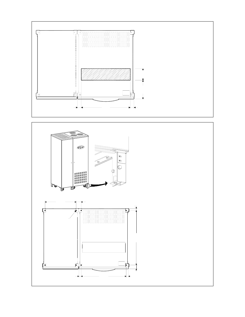
Fig. 3.4-2 Opening on the bottom of the cabinet for input and output cables
LP 33 Series opening is provided
on the bottom of the UPS for the
connection of input and output
cables.
Pay attention to the position of
this opening, when choosing the
placement of the UPS.
Fixing of the UPS cabinet LP 33 Series on the floor
LPS33U_030-040
_UPS fixing_02
Digital Energy
TM
L P Se ries
Fig. 3.4-3 Fixing of the UPS cabinet on the floor
654mm
536mm
32mm
25.5mm
1.79"
32mm
L
P
S
33U_030-
040_U
P
S
fi
xi
ng
_01
1"
25
.7
5"
45.5mm
21.10"
1.26"
1.26"
66.5mm
2.62"
Ø 10mm
Ø 0.40"
363mm
14.30"
Fig. 3.4-4 UPS cabinet floor fixing points
The UPS cabinet is free standing
and normally does not require to
be bolted to the floor.
The UPS cabinet can be fixed
however to the floor by bolting it
with the supporting blocks to the
floor.