3 battery connection, Ups with standard cabinet battery – GE Industrial Solutions LP 33 Series 30 & 40 kVA Installation Guide User Manual
Page 30
Modifications reserved
Page 30/41
OPM_LPS_3UI_30K_40K_0US_V010.doc
Installation Guide LP 33 Series 10-20 kVA
3.9.3 Battery
connection
Before proceeding to an external battery connection, follow the Safety rules concerning the battery.
Make sure that the UPS is not powered and remove the external battery protections.
NOTE !
To meet standards concerning electromagnetic compliance, the connection between
the UPS and external Battery must be done by using a shielded cable or suitable
shielded (metal) conduit!
List of possible battery configurations on LP 33 Series
Autonomy (min.)
Battery cabinet
Battery type
Block
number 30 kVA 40 kVA
Note
Standard cabinet battery
33 Ah – 12 V
24
10
8
See Fig. 3.9.3-1
Standard cabinet battery
33 Ah – 12 V
48
29
19
See Fig. 3.9.3-1
Standard cabinet battery
50 Ah – 12 V
24
19
12
See Fig. 3.9.3-1
Standard cabinet battery +
Additional cabinet 16.93” / 430mm
33 Ah – 12 V
96
(48+48)
65
44
See Fig. 3.9.3-2
Standard cabinet battery +
Additional cabinet 16.93” / 430mm
50 Ah – 12 V
48
(24+24)
45
33
See Fig. 3.9.3-2
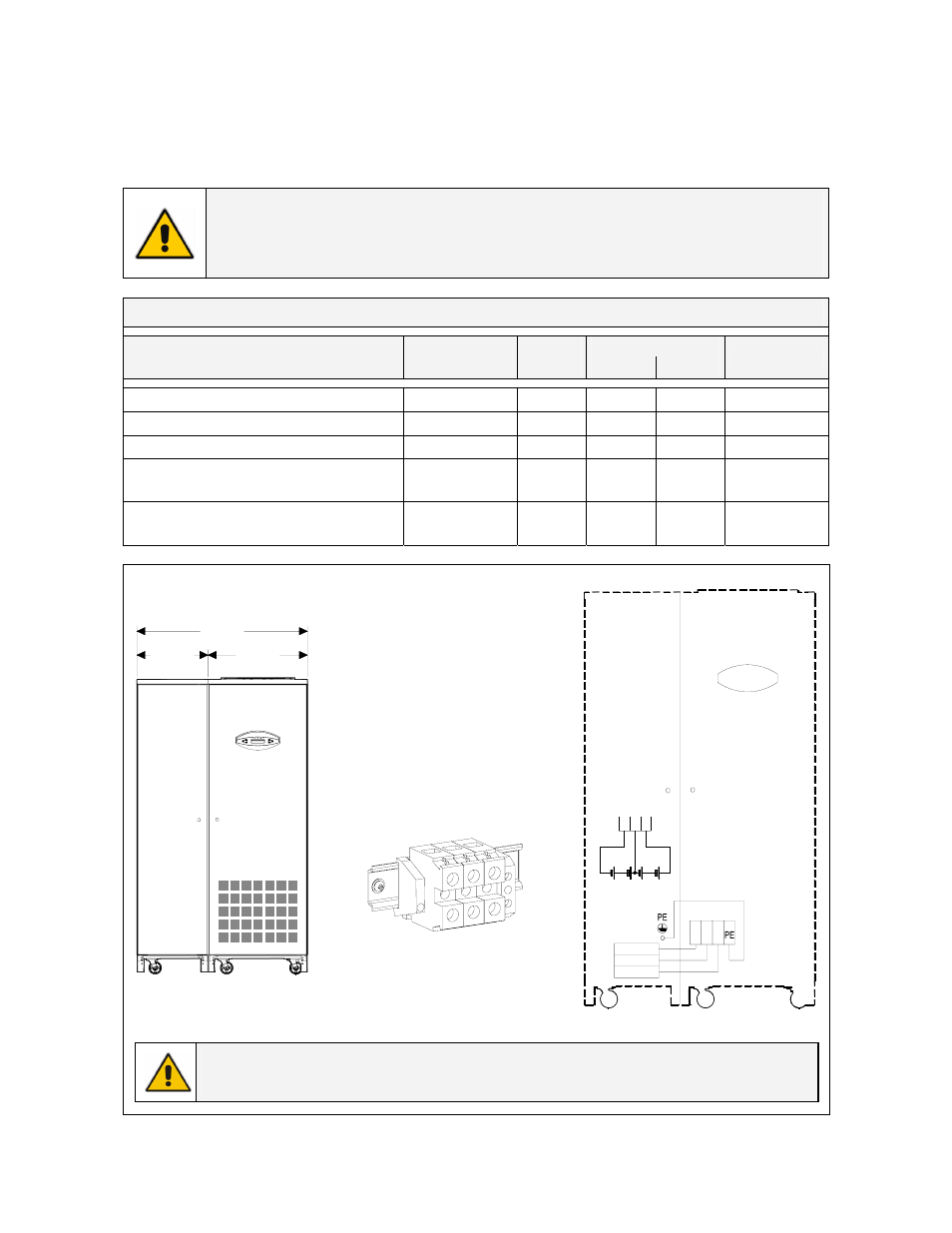
UPS with standard cabinet battery
X4 Battery - Battery connection
-
= Negative pole of the battery
0 = Central point of battery blocks
+ = Positive pole of the battery
PE = Battery cabinet ground
Battery
-
0
+
PE
LPS33U_
030-040_
Connectio
n battery
_01US
X4
23.63"
40.55"
16.93"
600mm
1030mm
430mm
LP 33 Series
Standard
battery
cabinet
LPS33U_030-040_UPS+Cabinet battery_01
LP
S33U_
030-
040_Ba
tter
y c
onnec
tion_Di
agram_0
1
LP 33 Series
Standard
battery
cabinet
F5
F6
F7
0
-
+
-
0 +
X4 - Battery
-
0
+
-
0
+
F7
F6 F5
X4 - Battery
Fig. 3.9.3-1 Diagram battery connection
Note !
The UPS unit is supplied with the battery connected as above showed on Fig. 3.9.3-1.