GE Industrial Solutions LP 33 Series 30 & 40 kVA Installation Guide User Manual
Page 24
Modifications reserved
Page 24/41
OPM_LPS_3UI_30K_40K_0US_V010.doc
Installation Guide LP 33 Series 10-20 kVA
3.7.4
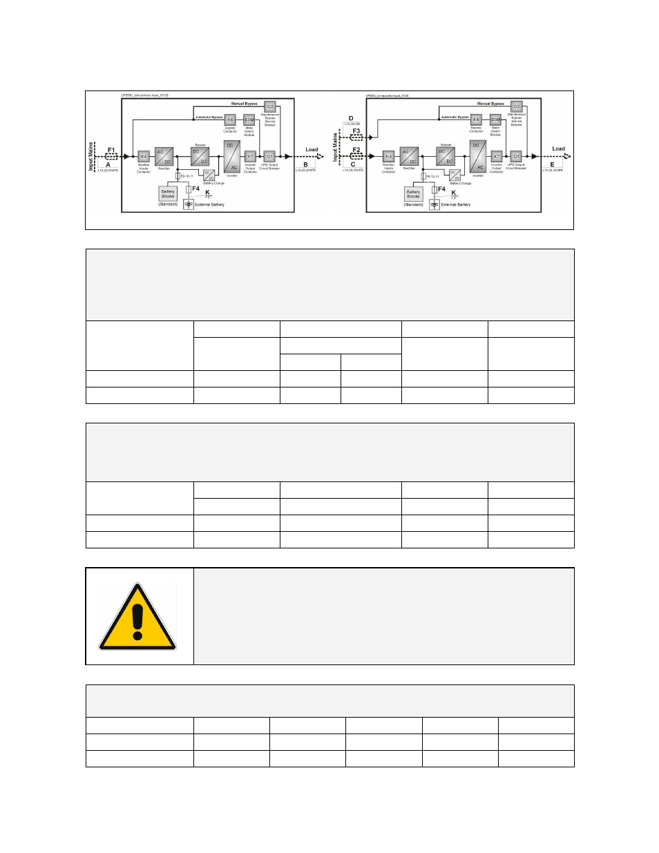
General dates table for current protection and wire sizing
Fig. 3.7.4-1 Common Input Rectifier & Bypass
Fig. 3.7.4-2 Dual Input Rectifier & Bypass (option)
The AC values below are current ratings per phase.
These maximum and nominal ratings should be considered when choosing the
appropriate AC over current protection device.
NEC (National Electric Code) Section 210-20 a rules must be applied.
DC current rating is the maximum battery discharge current which the UPS allows.
AC Input
AC Input Rectifier
AC Input Bypass
DC Input
F2
UPS Model
F1
Nom. Max.
F3 F4
LP 33 Series / 30 kVA
83.3 A
74 A
90 A
83 A
90 A
LP 33 Series / 40 kVA
111 A
98.7 A
120 A
111 A
120 A
Size of Branch Circuit Over current Protection - All Models:
"CAUTION - To reduce the risk of fire, only connect UPS to a circuit provided with (see below)
maximum amperes branch circuit over current protection in accordance
with the NEC (National Electric Code), NSI / NFPA 70
AC Input
AC Input Rectifier
AC Input Bypass
DC Input
UPS Model
F1 F2 F3
F4
LP 33 Series / 30 kVA
120 A
120 A
120 A
120 A
LP 33 Series / 40 kVA
150 A
150 A
150 A
150 A
Wire sizing according to NEC Section 210-20 (a) Table 310-16
Use 75°C (167°C) copper wire
Wiring requirements:
AC INPUT:
3-Phase, 4 wire plus Ground
AC OUTPUT:
3-Phase, 4 wire plus Ground
DC INPUT:
3 wire (positive, negative and neutral) plus Ground
Maximum cable diameter that terminals can accept.
Refer to torque specifications table for torque requirements.
UPS Model
Rectifier Input
Bypass Input
DC Input
AC Output
GND
LP 33 Series / 30 kVA
1 AWG
1 AWG
1 AWG
1 AWG
1 AWG
LP 33 Series / 40 kVA
4/0 AWG
4/0 AWG
4/0 AWG
4/0 AWG
4/0 AWG