5 ventilation and cooling – GE Industrial Solutions LP 33 Series 30 & 40 kVA Installation Guide User Manual
Page 18
Modifications reserved
Page 18/41
OPM_LPS_3UI_30K_40K_0US_V010.doc
Installation Guide LP 33 Series 10-20 kVA
3.5 VENTILATION
AND
COOLING
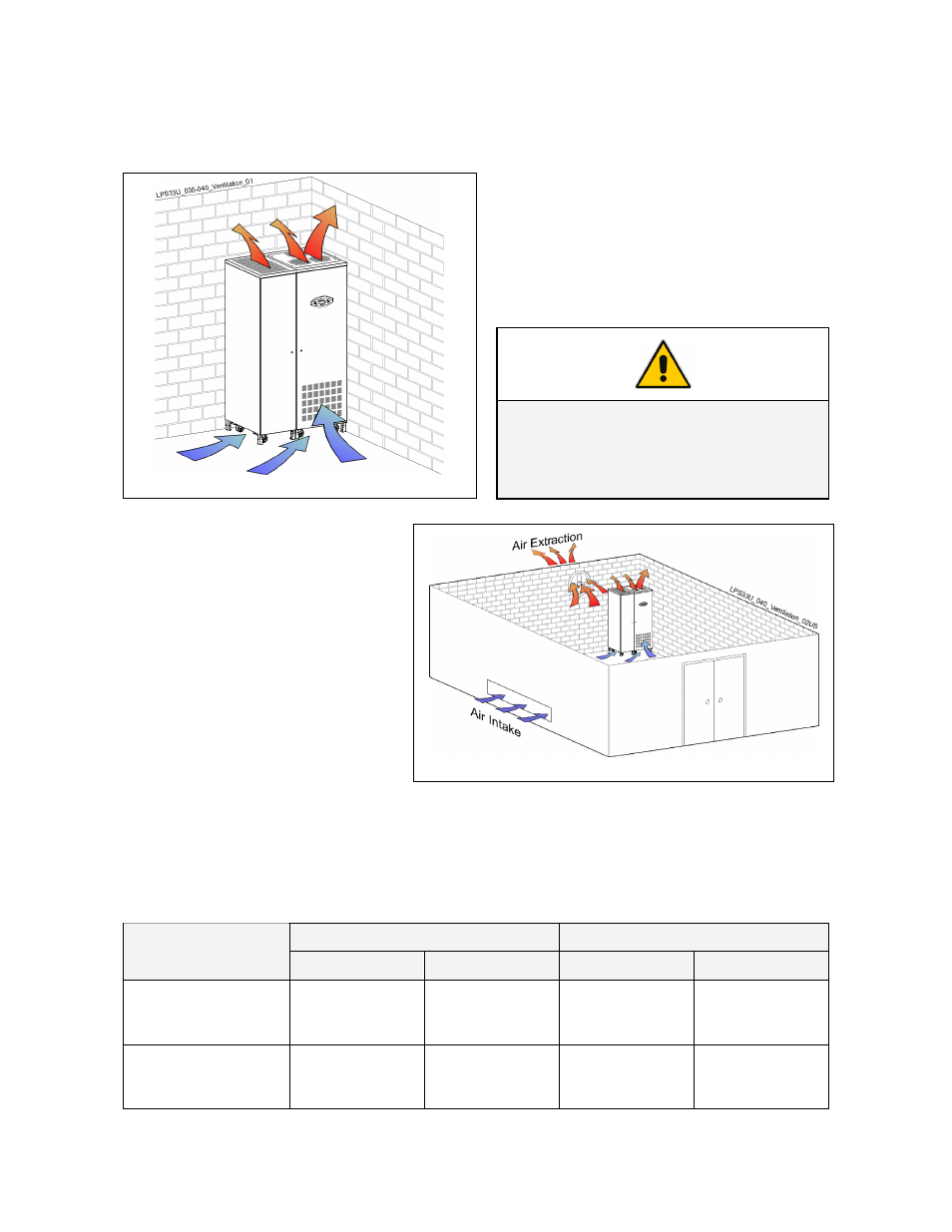
The heat produced by the UPS is transferred to the environment by its internal blowers.
Airflow through the UPS
It is important that the cooling air can freely flow
through the air inlets and outlets of the UPS.
Fig. 4.5-1 Airflow through the LP 33 Series
NOTE !
Do not put any object on the top of the
cabinet: it might obstruct the air flow.
Heat evacuation from UPS room
The heat must be evacuated from the
environment with a proper cooling /
ventilation system provided by the
user.
Fig. 4.5-2 Heat evacuation from UPS room
Air volume and losses of the UPS
The approximate minimum air volume needed to evacuate the heat generated by the UPS, for inlet
temperature max. 35°C (95°F), for the standard version at inverter nominal load with PF = 0.8 lag. and
battery charged, are the following:
Losses
Cooling air flow
UPS model
VFI Mode
ECO Mode
VFI Mode
ECO Mode
LP 33 Series / 30 kVA
8,874 BTU/hr
2.60 kW
1,673 BTU/hr
0.49 kW
448
CFM
760 m
3
/h
86
CFM
145 m
3
/h
LP 33 Series / 40 kVA
11,946 BTU/hr
3.50 kW
2,253 BTU/hr
0.66 kW
601
CFM
1,020 m
3
/h
115
CFM
195 m
3
/h