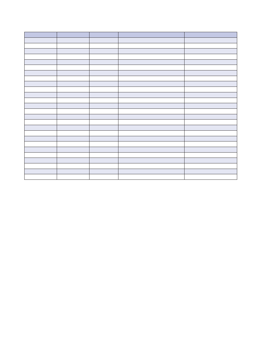
Table 5-1 debug registers definitions – GE Industrial Solutions EntelliPro ES User Manual
Page 232
CHAPTER 5: WinESG
EP OS MOTOR MANAGEMENT SYSTEM – INSTRUCTION MANUAL
5.3
6
Element
Type
Size
Description
Notes
TA10
Input
Bit
Maximun switch time (limit switch) - Timer
Use on motor starter typicals only
TA11
Input
Bit
Maximun soft starter time - Timer
Use on motor starter typicals only
TA12
Input
Bit
Maximunsoft stop time - Timer
Use on motor starter typicals only
TA13
Input
Bit
Phase loss delay - Timer
Use on motor starter typicals only
TA14
Input
Bit
Unbalance load delay - Timer
Use on motor starter typicals only
TA15
Input
Bit
Undercurrent delay - Timer
Use on motor starter typicals only
TA16
Input
Bit
Overcurrent delay - Timer
Use on motor starter typicals only
ZA1
Input
Bit
Counter 1 Expired Flag
ZA2
Input
Bit
Counter 2 Expired Flag
ZA3
Input
Bit
Counter 3 Expired Flag
ZA4
Input
Bit
Counter 4 Expired Flag
ZE1
Output
Bit
Counter 1 Start Flag
ZE2
Output
Bit
Counter 2 Start Flag
ZE3
Output
Bit
Counter 3 Start Flag
ZE4
Output
Bit
Counter 4 Start Flag
ZR1
Output
Bit
Reset Counter 1
ZR2
Output
Bit
Reset Counter 2
ZR3
Output
Bit
Reset Counter 3
ZR4
Output
Bit
Reset Counter 4
SE1
Input
Bit
0.5 Hz Flag
SE2
Input
Bit
1Hz Flag
SE3
Input
Bit
Reserved
SA1
Input
Bit
Contactor closure Counter Enabled Flag
Use on customized logic only
SA2
Output
Bit
Motor Speed Flag
Use on customized logic only
SA3
Output
Bit
Parameteriztion Allowed Flag
Use on customized logic only
SA4
Input
Bit
Reserved
Table 5-1 Debug registers definitions