Replacing a 596a rectifier fan assembly, Gps4812 replacement procedures, continued – GE Industrial Solutions Galaxy Verification User Manual
Page 85
Galaxy Power System Verification Procedures
Issue 3 January 2008
Replacement Procedures 4 - 17
GPS4812 Replacement Procedures, continued
Installing or
Replacing a 596A
Rectifier, continued
Step
Action
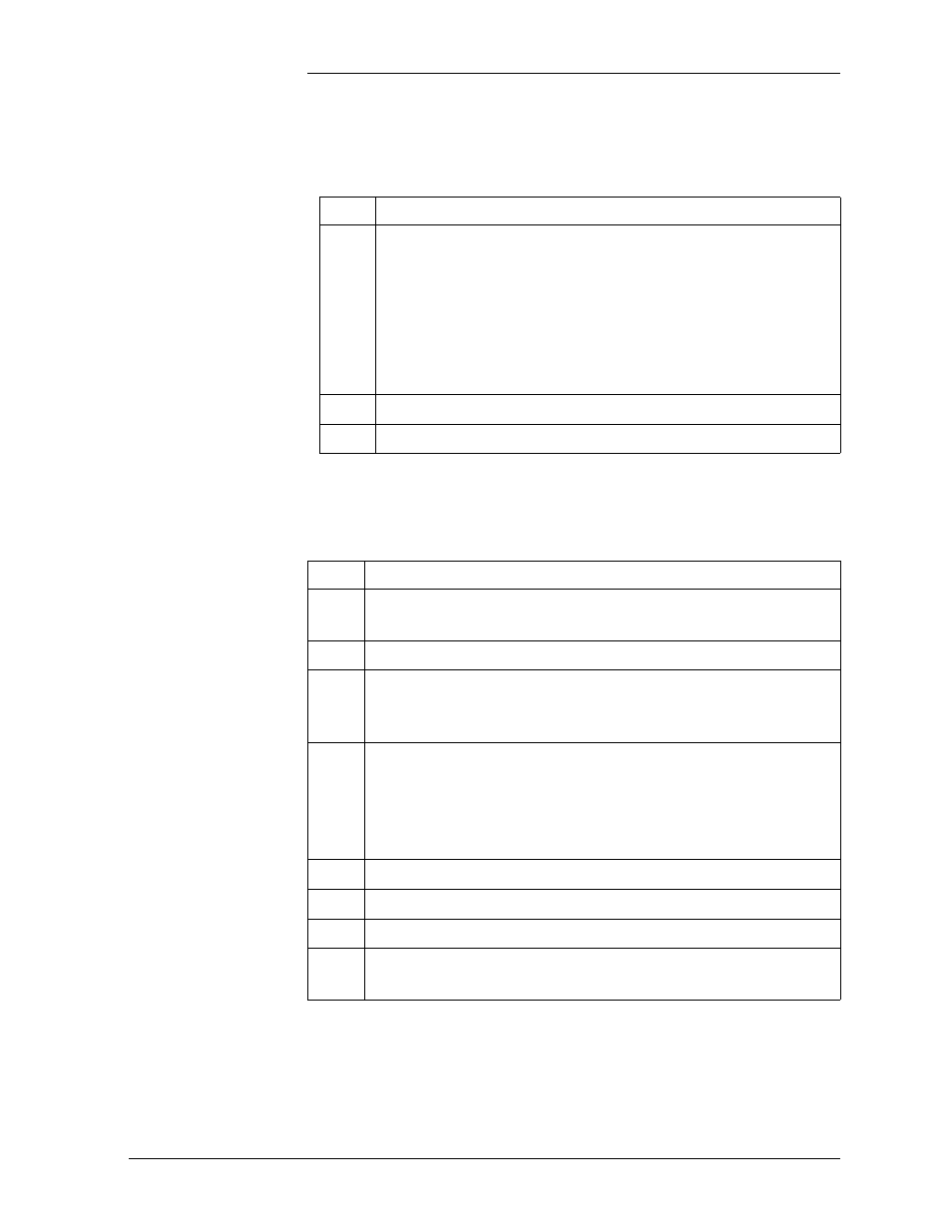
7
Once the rectifier has been installed, set the rectifier ID.
Follow the directions in product manual.
Note: The red LED on the rectifier will blink until the
rectifier establishes communication with the controller.
After communication is established, the controller will issue
a RECT MAJ alarm until the rectifier ID is set.
8
Turn the ac service back on.
9
Turn the rectifier’s ON/STBY switch to ON.
!
Replacing a 596A
Rectifier Fan
Assembly
Stop! Review the “Installing or Replacing a Rectifier” procedure in this
section before proceeding.
Step
Action
1
Remove the rectifier from the system. See the “Installing or
Replacing a Rectifier” procedure in this section.
2
WAIT five minutes for capacitors to discharge.
3
Loosen the white front cover by removing 14 screws (5 top,
5 bottom, 2 on each side). Before fully removing the cover,
disconnect the ribbon cable from the display circuit pack.
4
Remove the screws attaching the old fans to the chassis and
carefully unplug the fan connector. The fan connector is keyed
and can be loosened by inserting a screwdriver into the slotted
side of the connector and gently prying the fan-side connector
loose.
5
Replace the new fans.
6
Reconnect the ribbon cable removed in Step 3.
7
Attach the front cover.
8
Install the rectifier, following instructions in the “Installing or
Replacing a Rectifier” procedure in this section.