Replacing a 597a or 597b converter carrier, Figure 4-2: detail of converter components, Figure 4-3: cable connection between two converter – GE Industrial Solutions Galaxy Verification User Manual
Page 81: Carriers, Gps2424 replacement procedures, continued
Galaxy Power System Verification Procedures
Issue 3 January 2008
Replacement Procedures 4 - 13
GPS2424 Replacement Procedures, continued
Replacing a 597A
or 597B Converter
Carrier
Note: This procedure will disconnect the 48V output from the load even
if two carriers are being used.
Step
Action
1
Open the carrier door.
2
Remove all converter modules from the carrier to be replaced.
See “Replacing a Converter Module.”
3
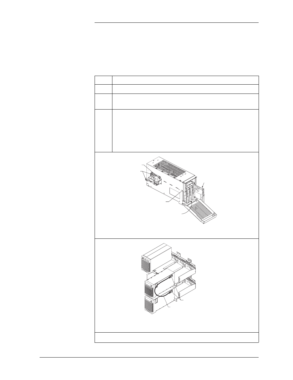
Locate the Allen-head retaining screw. See Figure 4-2. Using
the Allen wrench provided, rotate the tool counter-clockwise
to remove the old converter from the shelf.
Note: If two carriers are used, disconnect the shelf-to-shelf
cable as you slide out the carrier. See Figure 4-3.
Fan Latches
Fan Power
Connectors
Converter Interface
Card Retaining Screw
(opposite side)
Retaining Screw
47A Converter Module
Figure 4-2: Detail of Converter Components
848253654 Cable Assembly
Plug Cable into Converter Before
Sliding Converter onto Shelf
Note: Converters must be on adjacent shelves.
Figure 4-3: Cable Connection Between Two Converter
Carriers
Continued on next page.