GE Industrial Solutions Spectra RMS Molded Case User Manual
Page 12
GEH-702 Users Manual
11
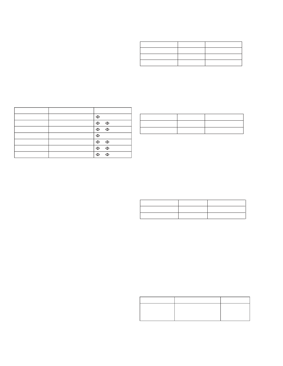
Catalog Number
Source Voltage Rating
Comments
ADSVMA120Y
120 Vac Wye conn.
to N potential
ADSVMA208Y
208 Vac Wye conn.
to
potential
ADSVMA240D
240 Vac Delta conn.
to
potential
ADSVMA277Y
277 Vac Wye conn.
to N potential
ADSVMA480Y
480 Vac Wye conn.
to
potential
ADSVMA480D
480 Vac Delta conn.
to
potential
ADSVMA600D
600 Vac Delta conn.
to
potential
Catalog Number
No. of Switch Elements
Switch Rating
SAUXGAB1
SAUXGAB2
1 form C
2 form C
Gold-Plated
Contacts
0.5 A @ 30 V
Voltage Modules
For Spectra Series
TM
Switchboard applications involving
Spectra microEntelliGuard
TM
breakers that require
control power and voltage signals, modules are
available that incorporate both the power supply and
voltage conditioner (see Table 9). The modules are 5
“X” units high (6
7
/
8
inches) and mount in 45-inch wide
distribution sections. The modules connect to the
vertical bus bars in the switchboard and provide control
power and voltage signals to the system.
Table 9. Voltage Module Catalog Numbers
Table 10. Distribution Cable Harness Options
Catalog Number
Length (in)
Wire Connectors
SDCHA11
11
12-Pin
SDCHA30
30
12-Pin
SDCHA60
60
12-Pin
Extension cables are used to increase the length of
an existing cable. Because the Spectra
microEntelliGuard
TM
breakers come with both 12-Pin
and 20-Pin wiring harnesses, there are two different
extension cables available.
Table 11. Extension Cable Harness Options
Voltage exchange cables are available and are
necessary for breakers with advanced metering when
installed in group-mounted equipment. These cables
connect between the breaker and the distribution cable
junction box and reverse the voltage signals being
Mounting a distribution cable junction box in the front
input to the breaker (from V
A
V
B
V
C
to V
C
V
B
V
A
). Refer to the
vertical upright of the switchboard across from the
Spectra microEntelliGuard
TM
breaker/trip unit permits
group mounting of the breaker. Group mounted
Spectra breakers with an auxiliary switch that connects
to a junction box require a 1 “X” filler plate adjacent
to the breaker’s right-hand side to accommodate the
auxiliary switch wiring.
Distribution and Extension Cables Interconnection
cables are required if equipment interfaces such as the
distribution cable junction box, power supply plate
assembly, voltage conditioner plate assembly are used.
These cables transmit electronic signals and/or control
power between the various interconnected
components. There are two different types of
interconnection cables available for Spectra
microEntelliGuard
TM
breakers – distribution cables and
extension cables.
Distribution cables are used to interconnect the
junction box, power supply plate assembly, and voltage
conditioner plate assembly. These cables have 12-
Pin connectors and are available in three different
lengths. Table 10 shows the different lengths and their
associated catalog numbers.
Phase Rotation description in the Setup Mode section
of this manual.
Table 12. Voltage Exchange Harness Options
Catalog Number
Length (in)
Wire Connectors
SDCAA6
6
12-Pin
SDCAA6C
6
20-Pin
Auxiliary Switches
An auxiliary switch is used to monitor the state of the
circuit breaker main contacts. Spectra
microEntelliGuard
TM
breakers with communications are
capable of communicating the breaker position when
an auxiliary switch is installed and connected via a
terminal board or junction box. Note: auxiliary switches
with gold plated contacts are required.
Table 13. Auxiliary Switch Options
Catalog Number
Length (in)
Wire Connectors
SDCEA30
30
12-Pin
SDCEA30C
30
20-Pin