Appendix b: s1024dw pin-outs and jumpers, J1 (d-25) connectors, J2 (d-sub-15) connectors – Ocean Optics S1024DW Install User Manual
Page 62
59
Appendix B: S1024DW Pin-outs and Jumpers
It is not necessary for the average user to worry about the interconnect scheme, as the cables supplied with all
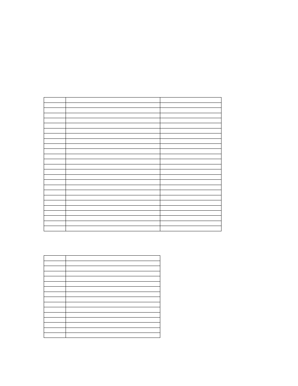
of the units need only be plugged into the matching connectors on the hardware. However, if the need arises
to design and fabricate your own cabling system, the following table supplies the necessary information.
J1 (D-25) Connectors
Pin
Function
A/D Pin Connection
1
Analog Channel 0
37
2
Analog Channel 1
36
3
Analog Channel 2
35
4
Analog Channel 3
34
5
Analog Ground
19
6
Reserved
7
N/C
8
N/C
9
Digital Ground
7
10
A/D Trigger Out
25
11
Master Clock In
20
12
Digital Ground
Not in Cable
13
+5VDC
1
14
Analog Channel 4
33
15
Analog Channel 5
32
16
Analog Channel 6
31
17
Analog Channel 7
30
18
Analog Ground
Not in Cable
19
N/C
20
Continuous Strobe In
8 (or use internal jumpers)
21
External Software Trigger Out (D3)
5
22
Spectrometer Mode Input S1
4
23
Integration Time Clock In
2
24
Strobe Enable, Spectrometer Mode Input S0
23
25
Enable Read In
3
J2 (D-SUB-15) Connectors
Pin
Function
1
Strobe Single Fire
2
Strobe Multiple Fire
3
+5VDC
4
External Hardware Trigger
5
External Synchronization Trigger
6
Analog Channel 7 Input
7
Analog Channel 6 Input
8
External Software Trigger (D3)
9
Analog Channel 1
10
Ground
11
Analog Channel 4
12
Analog Channel 5
13
Digital Out S0 (Strobe Enable or Lamp On/Off)
14
Analog Channel 3
15
Analog Channel 2