Bulb replacement, Specifications – Ocean Optics S1024DW Install User Manual
Page 12
9
Bulb Replacement
1. Order a replacement bulb, item D-1000-B, from Ocean Optics.
2. Make sure the D-1000 is turned off, the power cord is disconnected and the lamp has cooled.
3. Use a Phillips-head screwdriver to remove all 12 screws from the side panels of the D-1000 casing. Do
not remove any screws from the front, back, or bottom panels. Remove the cover.
4. Locate the deuterium bulb. It is located at the front of the housing, mounted on a black platform. Three
wires lead from the bottom of the bulb to the bright green electronic board: one red wire (with a time
indicator on it) and two black wires.
5. Use a Phillips-head screwdriver to loosen the screws securing these three wires to the green electronic
board. Once the screws are loose, gently remove the red wire and the two black wires. You do not need
to completely remove the screws to detach the wires. (Note that on the green electronic board, just
right of each wire, is a letter. To the right of the red wire is the letter “A”. To the right of one black
wire is the letter “H” and to the right of the second black wire is the letter “C”.)
6. In order to remove the bulb, you will need to unscrew the nut holding the collimating lens and SMA
connector in place. It is positioned in such a way that if the nut remains in place, you will not be able to
take out the deuterium bulb. Use a 3/8” wrench to remove the nut.
7. Use a Phillips-head screwdriver to remove the two screws securing the bulb to the black platform.
8. Remove the old bulb unit.
9. Inspect the new bulb unit, but avoid touching the glass casing (or envelope) around the bulb as the
oils from your skin will deteriorate the bulb. Inside the envelope is a triangle-shaped filament. The
filament has a square opening. The light passes through the square opening to the collimating lens.
Take the new bulb, carefully feeding the three wires through the hole in the black platform, and
position it so that the square opening in the filament faces the collimating lens.
10. Screw in the two screws that secure the bulb to the black platform.
11. Screw on the nut that holds the collimating lens in place.
12. Secure the three wires to the green electronic board. Attach the red wire to the top screw, labeled “A”.
Attach the black wires to the screws on the board labeled “H” and “C”. It does not matter which
black wire is attached to screw “H” or “C”.
13. Put the D-1000 cover back on and secure it with the 12 screws.
For directions on adjusting the focus of the collimating lens on the D-1000, turn to
Appendix A
.
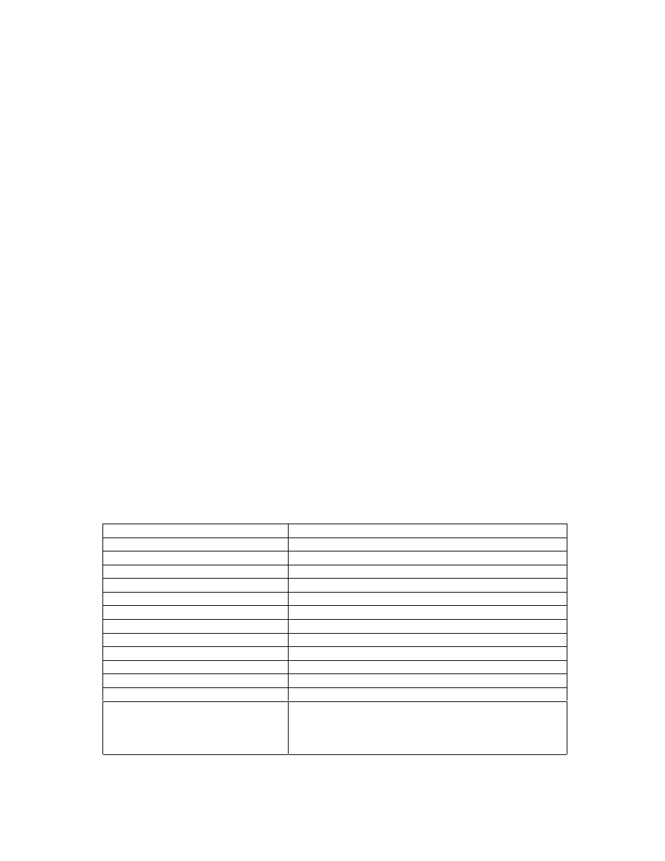
Specifications
Spectral range:
~200-400 nm
Time to stabilized output:
~30 minutes
Power consumption:
25-30 Watts
Bulb lifetime:
1,000 hours (replacement bulbs available)
Stability:
peak-to-peak = 0.05% (maximum); drift of +/-0.5%/hour
Aperture:
0.5 mm (at lamp)
Connector:
SMA 905
Window material:
0.4 mm thickness UV-transmissive glass
Lamp voltage:
85 volts DC (nominal)
Operating lamp current:
300 mA DC (+/- 1mA)
Timing:
microprocessor-based
Inputs:
trigger inputs for lamp (on/off)
Outputs:
levels for lamp (on/off), filament (on/off)
Power requirements:
120 volts AC @ 0.50 A, 50-60 Hz
220 volts AC @ 0.25 A, 50-60 Hz
100 volts AC @ 0.60 A, 50-60 Hz
240 volts AC @ 0.20 A, 50-60 Hz