Specifications – Ocean Optics S1024DW Install User Manual
Page 24
21
number, followed by FIB.LMP. The second file has the calibration numbers when calibrating with a
CC-3 cosine-corrector and fiber; its name contains the lamp’s serial number, followed by CC3.LMP.
7. Copy these two files into your OOIIrrad directory.
8. Start OOIIrrad by selecting Start | Programs | OOIIrrad | OOIIrrad.
9. Under the Lamp menu options, choose Select Lamp. A window opens in which you must choose the
Lamp Calibration report file that reflects your optical setup.
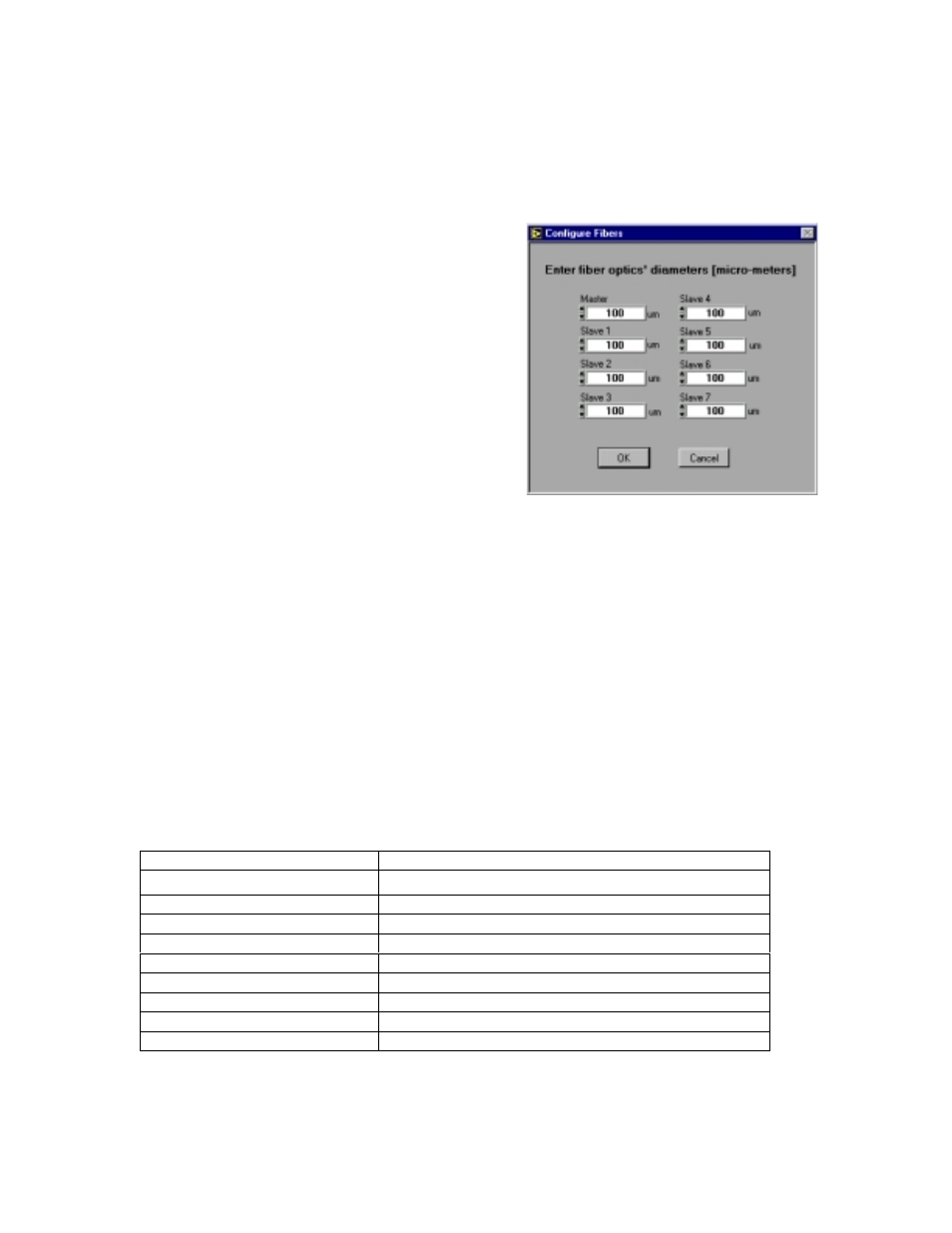
10. Under the Spectrometer menu function, choose
Configure Fibers. Enter the fiber diameter values for
each channel in your setup. If using a bare fiber, enter
the fiber’s diameter here. If using a fiber with a CC-3
cosine corrector, enter 3,900. Whatever optical setup
you wish to use for your application, you must also use
for your calibration. For example, if you are going to
use a 200
µ
m fiber with a CC-3 cosine corrector for
your application, you must use the same 200
µ
m fiber
and the same cosine corrector for your calibration.
11. To the right of the displayed spectrum, enter the
parameters for your setup next to
Scans to Avg
,
Smoothing Size
, and
Integration Period (ms)
.
•
Scans to Avg: Enter a value to implement a
sample averaging function that averages x number
of spectra. The higher the value, the better the
Signal-to-Noise.
•
Smoothing Size: Enter a value to implement a smoothing technique that averages across spectral
data. A value of 5, for example, averages each data point with 5 points to its left and 5 points to its
right. The greater this value, the smoother the data and the higher the S:N. However, if the value is
too high, a loss in spectral resolution will result.
•
Integration Period (ms): Enter a time in milliseconds to regulate the amount of time the detector
“looks” at the incoming photons. If your Scope Mode intensity is too low, increase this value. If
the intensity is too high, decrease the value. While watching the graph trace, adjust the integration
time until the signal intensity level is approximately 3500 counts.
12. Under Spectrometer menu options, choose Calibrate and then the channel you are calibrating.
13. A dialog box opens with the message “Verify lamp was ON for at least 15 minutes for a REFERENCE
scan.” Click OK. You have just taken your reference measurement.
14. Another dialog box opens with the message “Block light path to spectrometer for a DARK scan.”
Before clicking OK, be sure to block the light path by inserting an opaque object into the lamp’s filter
slot. Do not turn the lamp off. Click OK.
15. The spectrometer is now calibrated.
Specifications
Spectral range (calibrated):
360-1050 nm
Dimensions:
9.0 cm x 5.0 cm x 3.2 cm (LWH); 3.5
”
x 2.0
”
x 1.25
”
(LWH)
Power input:
12 VDC/800 mA (regulated)
Power output:
6.5 watts
Bulb life:
900 hours (recalibrate after ~50 hours of use)
Bulb color temperature:
3100K
Output to bulb:
5 volts/1.3 amps
Output regulation:
0.2% voltage
Time to stabilized output:
~30 minutes
Connector:
SMA 905