Indicator leds, Table 6 - led indicators, 5 indicator leds – B&B Electronics APXN-Q5428 - User Manual User Manual
Page 15
AirborneM2M™ Users Guide
B&B Electronics, Inc.
1/9/2014
15
6
The device will restart with the installed OEM defaults. If no OEM configuration
exists the device will return to B&B Electronics factory defaults.
See section 11.6 on use of OEM factory configurations.
The AirborneM2M
™ Default button is on the Ethernet/Power end of the box, next
to the 2.1mm barrel connector (See section 8.0)
5.5
Indicator LEDs
The indicator LEDs provide feedback on the state of the device when it is
configured as an AP/WR. If the device is configured for any other operation
please refer to the appropriate device manual. The LEDs are a useful tool during
installation and troubleshooting.
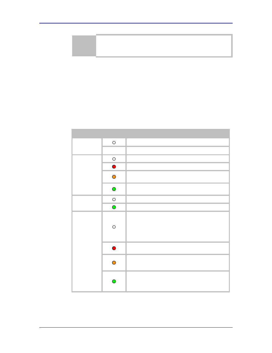
Table 6 - LED Indicators
LED
Color
Airborne Device State
POWER
Adapter is not powered.
(Blue) Adapter is powered.
POST
Adapter is not powered.
(Red) Adapter failed Power On Self Test (POST).
(Orange) Adapter passed POST but is not configured for
wireless network communication.
(Green) Adapter passed POST and is configured for wireless
AP communication.
LINK
Adapter is not powered or the Wireless radio is off.
(Green) Adapter is powered and the Wireless radio is on.
COMM
• If Power LED and COMM LED are both Off the Adapter is not
powered.
• If Power LED is On but the COMM LED is Off, it means that
an Ethernet link has been detected, but no TCP session from
the WLAN or Ethernet interface has been established. The
LED will flash Red when Ethernet network traffic occurs.
(Red) The device is powered and no Ethernet link has been
detected.
(Orange) A TCP connection to the adapter has been
established from the Wireless interface and no Ethernet link
has been detected.
(Green) A TCP connection to the adapter has been established
from the Wireless or Ethernet interface. An Ethernet link has
been detected. The LED will flash Orange when Ethernet
network traffic occurs.